
Gas landmark decomposition product quickly detecting device and method of SF6 equipment after failure

A technology of equipment failure and SF6, which is applied in the field of electric power safety production, can solve problems such as personal health and safety threats, data overrun, inflexibility, etc., and achieve the effects of rapid recovery of detection capabilities, improvement of work efficiency, and reduction of recovery time

Pending Publication Date: 2020-02-14
STATE GRID ZHEJIANG ELECTRIC POWER CO LTD SHAOXING POWER SUPPLY CO
View PDF11 Cites 2 Cited by
  • Summary
  • Abstract
  • Description
  • Claims
  • Application Information

AI Technical Summary

Problems solved by technology

[0005] 2. Disadvantages in the use of the SF6 decomposition product detection device at the present stage
After the data exceeds the range, the decomposition values ​​cannot be displayed correctly, and only one report of data exceeding the limit can be given when reporting the data.
It cannot provide good data support for analyzing the internal fault types of equipment
[0008] 2. Large-scale sensor collection type SF6 decomposition product detection device. The equipment pipeline is long and the internal sensor has high precision. It is easy to be polluted by a large amount of decomposition products generated by SF6 equipment failure, and it is difficult to restore the detection in a short time. Only by replacing the SF6 decomposition detection device can the detection be restarted
[0009] 3. It is inconvenient to use on-site for SF6 equipment failure emergency repair
At present, the large-scale sensor collection type SF6 decomposition product detection device is large in size, heavy, inflexible, and not portable. It needs to work with long pipelines and cable reels.
And because it takes a certain amount of time to build the entire detection system, the work efficiency is not high (including instrument power connection, instrument start-up preheating, long pipeline release and straightening, recovery device lap connection, joint tool replacement, etc.)
[0010] 4. When the SF6 equipment fails, the internal discharge will produce some highly toxic gases
If there is no SF6 gas recovery device, the health and safety of the staff around the equipment, such as maintenance tests, will be threatened
[0011] 5. The chemical adsorption reaction type SF6 decomposition product detection device, the use of the measuring glass tube and pipeline valve is not simple enough, and the data reading is inconvenient, which makes the on-site use a lot of inconvenience
In addition, the material in the related measurement glass tube has a service life and is a one-time consumable
And it's just a qualitative test

Method used


Image

  • Gas landmark decomposition product quickly detecting device and method of SF6 equipment after failure
  • Gas landmark decomposition product quickly detecting device and method of SF6 equipment after failure
  • Gas landmark decomposition product quickly detecting device and method of SF6 equipment after failure

Examples


Embodiment 1

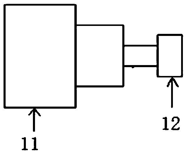
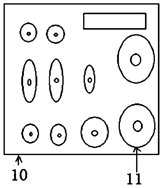
[0057] refer to Figures 1 to 10 As shown, a rapid detector of gas marker decomposition products after SF6 equipment failure, which includes:

[0058] Connector combination 1, including multi-type connectors 11 connected to SF6 equipment, each multi-type connector is connected to a quick-plug connector female 12;

[0059] The detection host 2 includes a detection host housing 20 with a detection cavity, an air intake quick-plug connector male 201 and an exhaust gas quick-plug connector female 202 connected to the detection host housing, and the air intake quick-plug connector male 201 is located at the detection host The air inlet position is connected with the quick plug joint female 12, and is used to introduce SF6 decomposition product gas. The H2S sensor 23, the SO2 sensor 24, the single-chip microcomputer 28, and the power module 29 are arranged in the detection chamber. A display screen 22 and a power switch 21 are provided, and the power supply module supplies power to...

Embodiment 2

[0090] refer to Figure 6 and Figure 9 Shown, a kind of SF6 equipment failure after the rapid detection method of gas marker decomposition products, using a kind of SF6 equipment failure in embodiment one gas marker decomposition product fast detector for detection, including the following steps:

[0091] First, the active air pump is turned on, the air enters the gas mixing chamber / valve through the gas pipeline through the controllable flow valve, and the measured gas also enters the gas mixing chamber / valve through the gas pipeline through the controllable flow valve;

[0092] Secondly, the measured gas is quickly detected through the sensor, and the single-chip microcomputer processes the measurement data and displays the measurement results on the display;

[0093] Finally, the measured gas is discharged through the gas outlet of the detection host, and the tail gas is collected through the gas collection device, or the tail gas is processed through the filter adsorptio...


PUM


Abstract

The invention discloses a gas landmark decomposition product quickly detecting device and method of SF6 equipment after failure. The gas landmark decomposition product quickly detecting device of theSF6 equipment after failure includes a connector combination, a detecting host, and a filtering and adsorption device; the connector combination includes multi-type connectors connected to the SF6 equipment, and each multi-type connector is connected to a quick plug connector female; in the detecting host, an air inlet quick plug connector male is connected to the quick plug connector female, a H2S sensor and a SO2 sensor are used for detecting H2S gas and SO2 gas separately, and a single chip processes the measurement data of the H2S sensor and the SO2 sensor and displays the measurement result on a display screen; and the filtering and adsorption device processes the exhaust gas. The gas landmark decomposition product quickly detecting device and method of the SF6 equipment after failureimproves the quick response capability of the detection and positioning work in a SF6 equipment fault field, and improves the safety of the detection work in the SF6 equipment fault field.

Description

technical field [0001] The invention belongs to the technical field of electric power safety production, and in particular relates to a detection instrument that can be used for rapid fault location and fault type analysis in SF6 equipment repair operations. Background technique [0002] In recent years, with the gradual expansion of the scale of substations and the gradual increase in the number of SF6 substation equipment, SF6 equipment failures have also increased. At the same time, the requirements for power supply reliability are getting higher and higher, and the urgency of emergency repair work is also getting higher and higher. SF6 gas insulated combined electrical appliances, referred to as GIS equipment, has been adopted on a large scale in recent years. At this stage, the large-scale sensor collection type SF6 decomposition product detection device can adapt to the daily SF6 equipment status detection work (applicable to the normal operation of the equipment or t...

Claims


Application Information

Patent Timeline
IPC IPC(8): G01N33/00
CPCG01N33/0031
Inventor 陈铭炜倪钱杭陈子宣朱明良李国栋王涛邱琼
Owner STATE GRID ZHEJIANG ELECTRIC POWER CO LTD SHAOXING POWER SUPPLY CO
Learn More