Calculating method of restrictive boolean network degeneracy
A Boolean network, computing method technology, applied in computing, special data processing applications, instruments, etc., to solve problems such as system paralysis or degradation
- Summary
- Abstract
- Description
- Claims
- Application Information
AI Technical Summary
Problems solved by technology
Method used
Image
Examples
Embodiment 1
[0050] Embodiment 1, a formula for calculating the degeneracy of a suppressed Boolean network.
[0051] The main idea of the degeneracy measurement of the suppressed Boolean network is to measure the overlapping amount of the contribution of all node sets to the overall function of the suppressed Boolean network (or called the overlapping amount of functional contribution).
[0052] The suppressive Boolean network includes an input layer, a transduction layer and an output layer, and it is assumed that the input layer has l nodes, the transduction layer has m nodes, and the output layer has t nodes. The m nodes in the transduction layer are grouped and divided into collections (or node collections), k is the collection size, representing the number of nodes contained in a collection, 1≤k≤m; the divided collections are grouped according to the collection scale, that is, those with the same number of nodes Sets are grouped into one group, and the grouping with a set size of ...
Embodiment 2
[0059] Embodiment 2, a method for calculating the degeneracy of a suppressed Boolean network.
[0060] The calculation method of the suppressed Boolean network degeneracy provided by the present invention comprises the following steps:
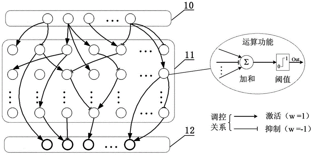
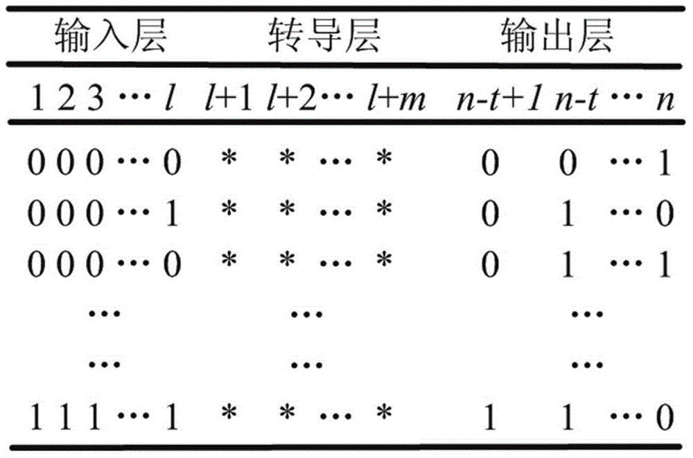
[0061] The first step is to clarify the inhibitory Boolean network (such as figure 1 shown), calculate the truth table of the target function of the inhibitory Boolean network.
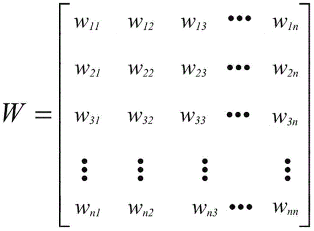
[0062] Such as figure 1 As shown, the suppressive Boolean network is recorded as a vector F=(V, W), V represents the set of all nodes in the network, and W represents the weight matrix of the regulatory relationship between nodes. The suppressive Boolean network is divided into an input layer 10 , a transduction layer 11 and an output layer 12 . In the biological network, the input layer 10 nodes represent signal perception receptors on the cell surface, which are used to sense external environmental stimuli; the transduction layer 11 nodes represent signal transdu...
Embodiment 3
[0085] Embodiment 3, a method for calculating the degeneracy of a suppressed Boolean network.
[0086] A suppressive Boolean network is known. The input layer has l=2 nodes, the transduction layer has m=7 nodes, and the output layer has t=3 nodes. The network topology is as follows Figure 5 shown.
[0087] The first step, calculate according to formula (3) in embodiment 2 Figure 5 The state value of each node in the suppressed Boolean network shown is obtained, Figure 5 See Table 2 for the truth table of the target function of the suppressed Boolean network shown.
[0088] Table 2: Figure 5 The truth table of the target function for all nodes
[0089]
[0090]
[0091] step two, yes Figure 5 In the suppressed Boolean network shown, the transduction layer nodes are divided into sets, and all the divided sets are grouped according to the set size.
[0092] Figure 5 The transduction layer of the suppressed Boolean network shown has 7 nodes (node numbers are 1...
PUM
 Abstract
Description
Claims
Application Information
 - R&D
- Intellectual Property
- Life Sciences
- Materials
- Tech Scout
- Unparalleled Data Quality
- Higher Quality Content
- 60% Fewer Hallucinations
Browse by: Latest US Patents, China's latest patents, Technical Efficacy Thesaurus, Application Domain, Technology Topic, Popular Technical Reports.
© 2025 PatSnap. All rights reserved.Legal|Privacy policy|Modern Slavery Act Transparency Statement|Sitemap|About US| Contact US: help@patsnap.com


