Al technical title is built by PatSnap Al team. It summarizes the technical point description of the patent document.
A technology of sound sensor and optical fiber sensor, which is applied in the direction of instruments, alarms, anti-theft alarms, etc., can solve problems such as false alarms, waste of security manpower, and insufficient positioning accuracy, and achieve the effect of reducing the rate of false alarms and false alarms
Active Publication Date: 2017-09-12
WUHAN FINEMEMS
View PDF8 Cites 0 Cited by
Summary
Abstract
Description
Claims
Application Information
AI Technical Summary
This helps you quickly interpret patents by identifying the three key elements:
Problems solved by technology
Method used
Benefits of technology
Problems solved by technology
However, the positioning accuracy of this kind of fiber optic sensor is generally tens of meters or even hundreds of meters. For some occasions with very strict security requirements, this positioning accuracy is not enough, which is not conducive to the security personnel to quickly and accurately find and deal with intrusions. By
Because fiber optic sensors are generally embedded in strips, the sensing area in the lateral direction is relatively small, and intentional intruders can easily cross the fiber optics, causing leakage alarms
In addition, the monitoring system that uses distributed optical fiber sensors alone will inevitably misjudgment some disturbance signals due to reasons such as inability to obtain intruder images or defects in the intrusion determination algorithm, resulting in false alarms, which will inevitably lead to a waste of security manpower
Method used
Image
Click on the blue label to locate the original text in one second.
Reading with bidirectional positioning of images and text.
Examples
Embodiment 1
[0017] Embodiments of the present invention are further described below in conjunction with the accompanying drawings:
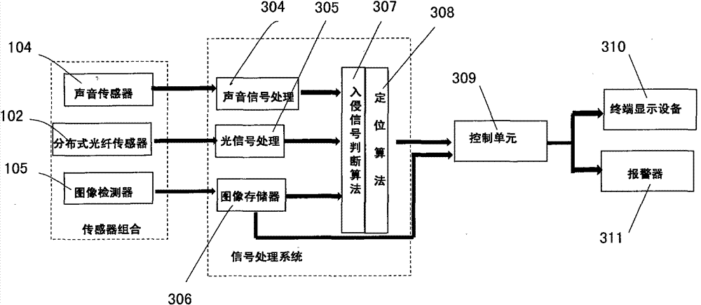
[0018] see image 3 , this embodiment is composed of a distributed optical fiber sensor 102 , an acoustic sensor 104 , an image detector 105 , a signal processing system, a control unit 309 , an alarm 311 and a terminal display device 310 . The signal processing system includes an optical signal processing module 305 , an audio signal processing module 304 , an image memory 306 , and judgment modules, ie, an intrusion location algorithm circuit 307 and a location algorithm circuit 308 .
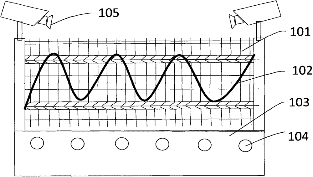
[0019] figure 1 Shown is a schematic layout diagram of the distributed optical fiber sensor 102, the sound sensor 104 and the image monitor 105 in the first embodiment. The distributed optical fiber sensor 102 is fixedly installed on the fence 101 in a wave shape, and the sound sensor 104 that has been treated with moisture and corrosion resistance is installed in a strai...
Embodiment 2
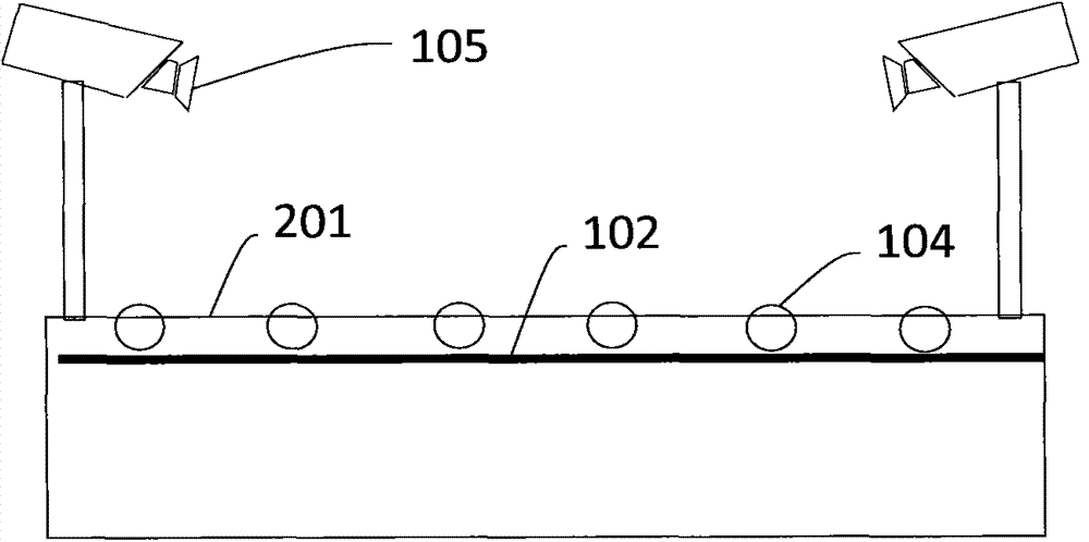
[0022] Embodiment 2 is the same as Embodiment 1, except that the sensor layout is different. The distributed optical fiber sensor 102 is arranged on the surface of the ground 201 or at a relatively shallow position under the surface, and it should be ensured that the disturbance can be monitored normally. The acoustic sensor 104 packaged with moisture and corrosion resistance is arranged on the surface of the ground 201 or at a relatively shallow position under the surface.
PUM
Abstract
The invention discloses a security and protection device integrated with an optical fiber sensor, a sound sensor and an image monitor. The security and protection device integrated with the optical fiber sensor, sound sensor and image monitor comprises the distributed optical fiber sensor, the sound sensor, an image detector, a signal processing system, a control unit, an alarm and terminal display equipment and is characterized in that the optical fiber sensor, sound sensor and image detector are arranged on a wall body, the signal processing system is connected with a light detector, a sound detector and the image detector through circuits, each of a light storage, a sound storage and an image storage is provided with a filter circuit, an amplifying circuit and an analog-digital conversion circuit, a judgment module is connected with each processing module through a circuit, the judgment module is connected with the control unit through a circuit, and the control unit is connected with an alarm and the terminal display equipment through circuits. The security and protection device integrated with the optical fiber sensor, sound sensor and image monitor combines the distributed optical fiber sensor, sound sensor and image detector, a system can duly and precisely obtain the position and image information of an invader, and the missing report rate and false alarm rate are reduced; the security and protection device integrated with the optical fiber sensor, sound sensor and image monitor is suitable for the regions, military installations and the like which have high requirements on confidentiality, security and protection.
Description
technical field [0001] The invention relates to a security device, in particular to a security device integrated with an optical fiber sensor, a sound sensor and an image monitor. Background technique [0002] With the continuous development of social economy, people have higher and higher requirements for the safety of life and environment. In terms of civilian use, especially when it comes to property and life safety, people hope to be able to predict the occurrence of disasters in time to avoid property losses; in terms of military defense, we have stricter requirements for the confidentiality of military information and military bases. Therefore, a security system with high accuracy is very necessary. [0003] For ordinary security systems, the current application is to set up several image monitors on the perimeter of the defense zone, which can realize real-time monitoring. For a large-scale, long-bordered security zone, this facility has the disadvantage of being un...
Claims
Application Information
Patent Timeline
Application Date:The date an application was filed.
Publication Date:The date a patent or application was officially published.
First Publication Date:The earliest publication date of a patent with the same application number.
Issue Date:Publication date of the patent grant document.
PCT Entry Date:The Entry date of PCT National Phase.
Estimated Expiry Date:The statutory expiry date of a patent right according to the Patent Law, and it is the longest term of protection that the patent right can achieve without the termination of the patent right due to other reasons(Term extension factor has been taken into account ).
Invalid Date:Actual expiry date is based on effective date or publication date of legal transaction data of invalid patent.