Protecting element
A technology for protecting components and melts, applied to electrical components, emergency protection devices, circuits, etc., can solve problems such as temperature rise and expansion, melt is easy to fuse, and performance improvement is limited, so as to improve breaking performance, avoid pollution, reduce The effect of destruction
- Summary
- Abstract
- Description
- Claims
- Application Information
AI Technical Summary
Problems solved by technology
Method used
Image

Examples
Embodiment 1
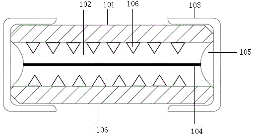
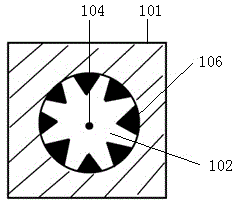
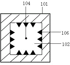
[0047] like figure 1The shown tubular structure protection element includes a tubular insulating casing 101, which has a cavity 102, and the fusible part of the melt 104 is suspended (the suspension referred to in the present invention means that the melt is not connected to the cavity except at both ends. The inner wall is in contact, therefore, even if the cavity is filled with other materials that are in contact with the melt, it should be regarded as the melt is suspended) Set in the cavity, electrodes are provided at both ends of the shell, and the electrodes can be as follows figure 1 In the metal end cap 103 shown, or other conventional structures, a stable electrical connection is formed between the metal end cap 103 and the melt 104 through soldering 105 . It must be pointed out that soldering 105 is not necessary, and those skilled in the art can also use glue to stick the melt 104 on the end cap 103, or clamp the melt through the tight fit between the end cap 103 an...
Embodiment 2
[0051] like Figure 8 ~ Figure 11 The shown multi-layer structure protection element includes an upper insulating layer 201, an intermediate insulating layer 202 and a lower insulating layer 203 from top to bottom, and electrodes 204 are provided at both ends of the upper, middle and lower insulating layers, and the electrodes are electrically connected to the melt 208 . Specifically, the electrodes include terminal electrodes located at both ends of each insulating layer and surface electrodes located on the upper surface of the upper insulating layer and / or the lower surface of the upper insulating layer, and the terminal electrodes and the surface electrodes are electrically connected. The intermediate insulating layer is arranged between the upper insulating layer and the lower insulating layer, the middle insulating layer is provided with a groove 205, and the middle of the intermediate insulating layer is longitudinally opened with a through hole 206, the wall of the thr...
Embodiment 3
[0055] like Figure 12 , Figure 13 , Figure 14 , Figure 15 The chip protection element shown includes an insulating substrate 305, an electrode part 301, a melt 302 and an insulating protective layer 304. The electrode part 301 is formed at both ends of the insulating substrate, and the insulating protective layer 304 covers between the electrodes at both ends of the insulating substrate. region, the electrode portion 301 can be exposed. Specifically, the electrode part 301 not only covers the two ends of the insulating substrate 305 but also extends to the front and back of the insulating substrate 305 (the present invention refers to Figure 12 One side of the insulating substrate shown in the above is the front side, and the opposite side is the back side), we will refer to the electrode part formed on the front side of the insulating substrate 305 as the positive electrode 3011, and the electrode part formed on the back side of the insulating substrate 305 as the bac...
PUM
 Abstract
Description
Claims
Application Information
 - R&D
- Intellectual Property
- Life Sciences
- Materials
- Tech Scout
- Unparalleled Data Quality
- Higher Quality Content
- 60% Fewer Hallucinations
Browse by: Latest US Patents, China's latest patents, Technical Efficacy Thesaurus, Application Domain, Technology Topic, Popular Technical Reports.
© 2025 PatSnap. All rights reserved.Legal|Privacy policy|Modern Slavery Act Transparency Statement|Sitemap|About US| Contact US: help@patsnap.com