Mobile terminal and antenna structure thereof

An antenna structure and mobile terminal technology, applied in the field of communication, can solve the problems of reducing antenna performance, difficulty in implementation, and high implementation cost, and achieve the effects of improving antenna performance, low implementation cost, and expanding antenna bandwidth

Active Publication Date: 2015-05-06
NUBIA TECHNOLOGY CO LTD
View PDF3 Cites 9 Cited by
  • Summary
  • Abstract
  • Description
  • Claims
  • Application Information

AI Technical Summary

Problems solved by technology

In order to expand the bandwidth of the antenna and improve the performance of the antenna, some solutions in the prior art realize the adjustable frequency of the antenna by designing a complex circuit structure, which is difficult to realize, high in cost and unstable in performance.
[0003] Moreover, in order to reduce the impact of the antenna on the human head, the main antenna of the mobile terminal is generally located at the bottom of the terminal, and electronic devices such as USB connectors and microphones are also placed at the bottom of the terminal, usually placed around or below the antenna, so that These electronic devices have a certain impact on the space and efficiency of the antenna, reducing the performance of the antenna

Method used


Image

  • Mobile terminal and antenna structure thereof
  • Mobile terminal and antenna structure thereof

Examples


Embodiment Construction

[0016] It should be understood that the specific embodiments described here are only used to explain the present invention, not to limit the present invention.

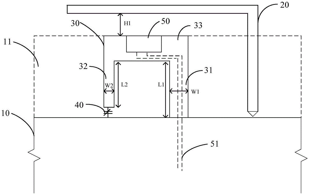
[0017] see figure 1 An embodiment of the antenna structure of the mobile terminal of the present invention is proposed. The antenna structure includes a main board 10 , an antenna body 20 and an antenna tuning circuit, wherein the antenna tuning circuit includes a tuning element 30 and a variable capacitor 40 .

[0018] The main board 10 is the main device and circuit placement area of ​​the mobile terminal, and the main material is copper and plate. The dotted line area in the figure is the empty area 11 of the main board 10, which is a part of the main board 10. This area 11 is generally not covered with metal, and mainly provides better radiation space for the antenna. Its size and shape can be changed according to actual needs.

[0019] The antenna body 20 is the radiation body of the antenna, which is connected ...


PUM


Abstract

The invention discloses a mobile terminal and an antenna structure thereof. The antenna structure of the mobile terminal comprises a main board and an antenna main body connected with the main board, and further comprises an antenna tuning circuit located between the main board and the antenna main body, wherein the antenna tuning circuit comprises a tuning piece and a variable capacitor, one end of the tuning piece is directly connected with the main board, and the other end of the tuning piece is bent, and then connected with the main board through the variable capacitor. Accordingly, the antenna structure of the mobile terminal influences tuning frequency of an antenna by adjusting capacitance value of the variable capacitor, achieves tuning of the frequency of the antenna, greatly broadens the bandwidth of the antenna, and improves efficiency of the antenna. A circuit structure of the antenna structure of the mobile terminal is simple, and easy to achieve, and accordingly the antenna structure of the mobile terminal achieves the purposes of being low in cost and stable in performance. Additionally, electron devices of a USB (universal serial bus) connector, a microphone and the like are placed on the tuning piece, influences of the electron devices of the USB connector, the microphone and the like on the antenna are effectively reduced, performance of the antenna is improved, and simultaneously improvement of self performance of the electron devices of the USB connector, the microphone and the like is facilitated.

Description

technical field [0001] The present invention relates to the field of communication technology, in particular to a mobile terminal and its antenna structure. Background technique [0002] With the rapid development of wireless communication technology, the mobile phone standard has changed from 2G to 3G and then to 4G. There are more and more antenna frequency bands, and the requirements for multi-frequency antennas are getting higher and higher. The demand for small-sized, multi-band antennas is getting stronger and stronger. . In order to expand the bandwidth of the antenna and improve the performance of the antenna, some solutions in the prior art realize the adjustable frequency of the antenna by designing a complex circuit structure, which is difficult to implement, high in cost and unstable in performance. [0003] Moreover, in order to reduce the impact of the antenna on the human head, the main antenna of the mobile terminal is generally located at the bottom of the ...

Claims


Application Information

Patent Timeline
Patent Type & Authority Applications(China)
IPC IPC(8): H01Q23/00H01Q1/38H01Q1/24
Inventor 程仕意
Owner NUBIA TECHNOLOGY CO LTD
Why Eureka
Try Eureka