Message transmission method and system

A message transmission and message technology, applied in the field of message transmission, can solve the problems of base station equipment being unable to connect to the core network, inflexible deployment, and unable to build a wired transmission environment for base station equipment.

Active Publication Date: 2015-05-06
DATANG MOBILE COMM EQUIP CO LTD
View PDF6 Cites 18 Cited by
  • Summary
  • Abstract
  • Description
  • Claims
  • Application Information

AI Technical Summary

Problems solved by technology

[0003] In the current networking form of the LTE system, for rural or remote mountainous areas, it is impossible to build a wired transmission environment for the base station equipment, resulting in the inability of the base station equipment to connect to the core network, hindering local communication, remote areas or shadow coverage areas, or even It is a blind area, and there is a problem of poor coverage
Furthermore, in some scenarios where optical fibers cannot reach or wired backhaul construction is difficult (such as urban micro-coverage scenarios without wired backhaul, indoor office environments without room distribution deployment, residential buildings where optical fibers cannot reach households, remote suburbs or rural areas) etc.), the coverage of the macro cell signal is weak, and the deployment is not flexible

Method used


Image

  • Message transmission method and system
  • Message transmission method and system
  • Message transmission method and system

Examples


Embodiment 1

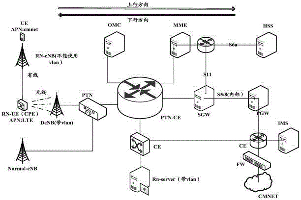
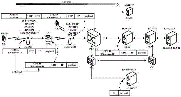
[0058] Embodiment 1 of the present invention provides a method for message transmission, which can be applied to a networking scenario of a Relay-like scheme, such as image 3 As shown, the method for message transmission specifically includes the following steps:

[0059] Step 301, the relay base station equipment receives the uplink message from the user equipment, encapsulates the GTPU header and the tunnel header on the uplink message, and sends the uplink message to the CPE.

[0060] Wherein, the source IP address of the tunnel header is the private network IP address of the relay base station equipment, the destination IP address is the IP address of the tunnel server, and the destination port is a specific listening port of the tunnel server. Further, the source port of the tunnel head can be any port, for example, the source port can be a port number allocated by the relay base station equipment from the pre-planned port pool of each application according to applicatio...

Embodiment 2

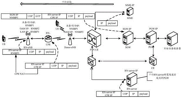
[0097] Based on the same inventive concept as the above-mentioned method, an embodiment of the present invention also provides a message transmission system, the system specifically includes: a relay base station device, configured to receive an uplink message from a user equipment, and transmit the uplink message The packet encapsulates the GTPU header and the tunnel header, and sends the uplink message to the CPE; the source IP address of the tunnel header is the private network IP address of the relay base station equipment, the destination IP address is the IP address of the tunnel server, and the destination port is the tunnel server IP address. The specific listening port of the server; CPE, used to receive the uplink message from the relay base station equipment, modify the source IP address of the tunnel header to the public network IP address of the relay base station equipment, and send the uplink message to the donor Base station DeNB; DeNB is used to receive the upl...


PUM


Abstract

The invention discloses message transmission method and system. The method comprises the steps of encapsulating a GTPU head and a tunnel head for an uplink message through a relay base station device; sending the uplink message to a CPE (Central Processing Element); modifying the source IP address of the tunnel head into the public network IP address of the relay base station device through the CPE; sending the uplink message to DeNB; encapsulating corresponding IP+UDP+GTPU head for the uplink message through the DeNB; sending the uplink message to an SGW (Signal Gate Way); de-encapsulating the IP+UDP+GTPU head encapsulated in the uplink message through the SGW; sending the uplink message to a tunnel server through the relay base station device according to the target IP address of the tunnel head, encapsulated in the uplink message; de-encapsulating the tunnel head encapsulated in the uplink message by the relay base station device through the tunnel server; sending the uplink message to the SGW; sending the uplink message to a target device through the SGW according to the target IP address of the uplink message. According to the method and system, the difficulty at deployment for wired transmission can be solved through the wireless transmission environment, and therefore, the problem of limitation on communication in some regions is avoided, the system coverage range is expanded, and the cell throughput is increased.

Description

technical field [0001] The present invention relates to the field of communication technology, in particular to a method and system for message transmission. Background technique [0002] Such as figure 1 As shown, it is a schematic diagram of networking of an LTE (Long Term Evolution, long-term evolution) system, which is divided into a wired side and a wireless side. The wired side includes service servers, core network, three-layer switch, transmission PTN (Packet Transport Network, packet transport network), etc., and the wireless side includes L1 / L2 (layer 1 / layer 2) protocol processing, radio frequency unit processing, UE (User Equipment , user equipment) receive and so on. [0003] In the current networking form of the LTE system, for rural or remote mountainous areas, it is impossible to build a wired transmission environment for the base station equipment, resulting in the inability of the base station equipment to connect to the core network, hindering local comm...

Claims


Application Information

Patent Timeline
Patent Type & Authority Applications(China)
IPC IPC(8): H04W16/26H04W28/06H04L12/46H04L29/12
Inventor 孙祎林坤
Owner DATANG MOBILE COMM EQUIP CO LTD
Why Eureka
Try Eureka