Adjustable constant flow source driving circuit for LED

A driving circuit and constant current source technology, which is applied in the field of adjustable constant current source driving circuits for LEDs, can solve problems such as forward current reduction, LED aging, shortened service life, etc., and achieve the effect of stable voltage output

Inactive Publication Date: 2015-05-06
CHANGZHOU WUJIN FENGTAI ELECTROMECHANICAL
View PDF3 Cites 11 Cited by
  • Summary
  • Abstract
  • Description
  • Claims
  • Application Information

AI Technical Summary

Problems solved by technology

[0003] The volt-ampere characteristics of LEDs are the same as those of ordinary diodes. Small fluctuations in forward voltage will lead to sharp changes in forward current. The magnitude of LED forward current will change with ambient temperature. When the environment reaches a certain temperature, The allow

Method used


Image

  • Adjustable constant flow source driving circuit for LED
  • Adjustable constant flow source driving circuit for LED

Examples


Example Embodiment

[0014] In order to enable those skilled in the art to better understand the solution of the present invention, and to make the above-mentioned objects, features and advantages of the present invention more obvious and understandable, the present invention will be further described in detail below with reference to the embodiments and the accompanying drawings.

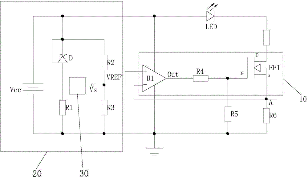
[0015] Such as figure 1 As shown, the present invention provides an adjustable constant current source drive circuit for LEDs, which includes a current series negative feedback system 10 composed of an operational amplifier U1 and a transistor FET, connected to the positive phase input terminal (+) of the operational amplifier U1 and respectively Input the reference voltage V to the positive input terminal (+) of the operational amplifier U1 REF The LED is connected between the drain D of the transistor FET and the reference voltage circuit 20 as a load output.

[0016] The reference voltage circuit 20 includes a power sup...


PUM


Abstract

The invention discloses an adjustable constant flow source driving circuit for an LED (light-emitting diode). The driving circuit comprises an operation amplifier, a transistor and a single chip system, wherein the positive phase input end of the operation amplifier is connected with a reference voltage circuit, the grid electrode of the transistor is coupled with the output end of the operation amplifier through a resistor R4, the LED is connected between the drain electrode of the transistor and the reference voltage circuit, the single chip system is connected with the positive phase input end of the operation amplifier, the source electrode of the transistor is connected with the negative phase input end of the operation amplifier to form a current-series negative feed-back system, a grounded voltage sampling resistor R6 is connected between the source electrode of the transistor and the negative phase input end of the operation amplifier, nodes A are formed between the source electrode of the transistor and a voltage sampling resistor R6, the single chip system is used for adjusting the control voltage of the positive phase input end of the operation amplifier according to the voltage signals acquired from the nodes A, and a grounded divider resistor R5 is connected between the resistor R4 and the grid electrode of the transistor. The driving circuit is controlled by the single chip system, thus current change can be steadily and continuously controlled when the voltage on the positive phase input end of the operation amplifier is adjusted.

Description

technical field [0001] The invention relates to an adjustable constant current source drive circuit for LEDs. Background technique [0002] In today's increasingly serious energy and environmental problems, LEDs with the characteristics of high efficiency, energy saving, environmental protection, and long life have gained people's attention. If LED lighting can replace the current low-efficiency and high-energy-consuming traditional lighting, it will undoubtedly alleviate The current increasingly urgent problems of energy shortage and environmental degradation play a decisive role. [0003] The volt-ampere characteristics of LEDs are the same as those of ordinary diodes. Small fluctuations in forward voltage will lead to sharp changes in forward current. The magnitude of LED forward current will change with ambient temperature. When the environment reaches a certain temperature, The allowable forward current of the LED will decrease sharply. In this case, if the large curre...

Claims


Application Information

Patent Timeline
IPC IPC(8): H05B37/02
Inventor 谢伟文
Owner CHANGZHOU WUJIN FENGTAI ELECTROMECHANICAL
Why Eureka
Try Eureka