Glass substrate strip

A technology of glass substrates and substrates, which is applied in glass molding, glass molding, glass manufacturing equipment, etc., and can solve problems such as damage

Active Publication Date: 2015-05-06
SCHOTT AG
View PDF8 Cites 7 Cited by
  • Summary
  • Abstract
  • Description
  • Claims
  • Application Information

AI Technical Summary

Problems solved by technology

The disadvantage here is that the thin glass layer can vibrate or be concaved downwards and thus be exposed to the risk of breakage

Method used


Image

  • Glass substrate strip
  • Glass substrate strip
  • Glass substrate strip

Examples


Embodiment Construction

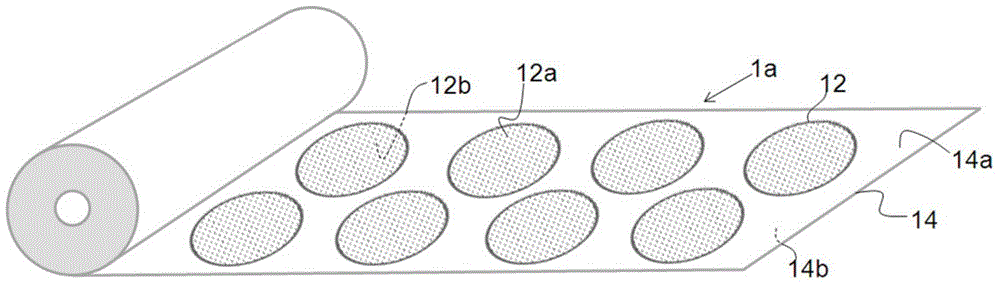
[0056] Figure 1a Shown by way of example is a glass substrate ribbon 1 a with positioned and fixed circular thin glass segments 12 for making wafers. The thin glass segment 12 has been fixed on an adhesive foil 14 in contact with the entire area of ​​the first thin glass surface 12b. The second thin glass surface 12a is uncovered, directed upwards, and comes into contact with the adhesive foil 14, ie with the surface 14b of the adhesive foil, only when the glass substrate strip 1a is wound. The thin glass segments have a thickness of 0.06 mm. The adhesive foil 14 is a coextruded polyethylene adhesive foil, provided as an example by PE-CLING Protect from Molco GmbH, Schwertter. The thickness of the adhesive foil is 110 microns, so the location of the neutral phase between tensile and compressive stresses in the rolled state is in the adhesive layer between the surface 14a of the adhesive foil and the surface 12b of the thin glass segment. The adhesive foil 14 has an adhesive...


PUM

PropertyMeasurementUnit
thicknessaaaaaaaaaa
thicknessaaaaaaaaaa
thicknessaaaaaaaaaa

Abstract

The invention relates to a glass substrate strip made of a multiplicity of thin-glass segments which are positioned and fixed on an adherent foil. The thin-glass segments are fixed on the adherent foil over the entire area thereof, by way of the entire edge region thereof or by way of parts of the edge regions thereof. The glass substrate strip can comprise lateral transport bands or else coding fields. For storage, it is plated in meandering fashion or is rolled up, and it serves not only for transport and storage but also as a carrier strip in processing steps for the thin-glass segments.

Description

technical field [0001] The present invention relates to a glass substrate ribbon consisting of a plurality of thin glass segments on an adhesive foil. Background technique [0002] Thin glass is increasingly used in many applications, for example in the field of consumer electronics, for example as a glass element for a protective cover for semiconductor modules, organic light-emitting diode light sources or thin or curved display devices, Or in the field of regenerative energy or energy engineering, for example for solar cells. Examples here are touch panels, capacitors, thin-film batteries, flexible circuit boards, flexible organic light-emitting diodes, flexible photovoltaic modules, electronic paper and also microelectromechanical systems (MEMS) or micro-opto-electromechanical systems (MOEMS). The increasing importance of thin glass in many applications is due to its excellent properties such as chemical resistance, resistance to temperature change cycles and thermal re...

Claims


Application Information

Patent Timeline
Patent Type & Authority Applications(China)
IPC IPC(8): B32B7/06B32B17/10B32B3/16
CPCB32B17/064B32B3/16B32B7/06B32B2457/20B32B17/10B65B15/04B65D73/02B65D85/48C03B17/064C03B33/02C03B17/06
Inventor 乌尔里克·纽哈尤泽尤尔根·沃格特斯蒂芬·扎克曼克里斯汀·格约尔克
Owner SCHOTT AG
Why Eureka
Try Eureka