
Wind power wave making aerator

An aerator and wave-making technology, which is applied in fish farming, application, animal husbandry, etc., can solve the problems that the wave amplitude cannot reach the expected value, the energy efficiency ratio has not been improved, and the wave amplitude is unbalanced, so as to improve the aeration effect , Amplitude balance, uniform circumferential swing effect

Active Publication Date: 2015-05-13
靖江市金标空调设备厂
View PDF12 Cites 7 Cited by
  • Summary
  • Abstract
  • Description
  • Claims
  • Application Information

AI Technical Summary

Problems solved by technology

In addition to driving the impeller to rotate, the gearbox of this type also needs to drive the rotating arm and counterweight to make the floating body sway, that is, the generation of waves also needs to obtain energy from the motor, so the power of the motor needs to be increased, and the energy efficiency ratio is lower. no improvement
In addition, because the length of the rotating arm is limited by the size of the waterproof cover, it cannot be made too long, so that the swing amplitude and the amplitude of the generated waves cannot reach the expected value; and due to the setting of the rotating arm and the counterweight, the motor is eccentric relative to the impeller shaft. The aerator is in an unbalanced state, resulting in unbalanced wave amplitude in the circumferential direction, that is, part of the swaying amplitude of the floating body is offset by the eccentric structure, which affects the aeration effect

Method used


Image

  • Wind power wave making aerator
  • Wind power wave making aerator
  • Wind power wave making aerator

Examples


Embodiment Construction

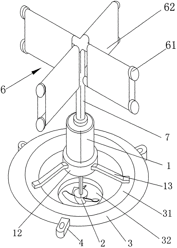
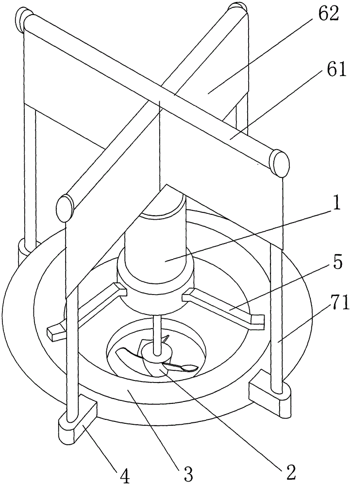
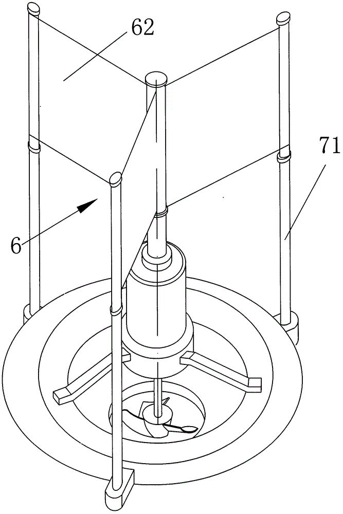
[0017] Such as figure 1 The first embodiment shown is a wind-powered wave-making aerator, including a motor 1, a reducer 12, an impeller 2 and a floating body 3, the output shaft of the reducer is the impeller shaft, and the motor and the reducer are fixed on the floating body 3 through a bracket 13 On the top, the positive triangle setting of the bracket can ensure that the motor and the floating body are coaxial; the motor is a fully enclosed structure, and the motor drives the impeller 2 to rotate through the reducer during operation, and the water splashed from the churning up is used to cool it. The floating body 3 is in the shape of a ring, and its inner ring surface is made into an inverted cone surface 31. The impeller 2 is installed at the lower part of the opening 32 of the inverted cone surface. Spray to increase the dissolved oxygen in water. On the outer wall of the floating body 3, there are 2-4 lugs 4 equidistantly distributed. The first function is to limit th...


PUM


Abstract

The invention provides a wind power wave making aerator which comprises a floating body and a motor fixedly installed on the floating body. The motor is coaxial with the floating body and drives an impeller to rotate through a speed reducer. Two to four lugs are manufactured on the periphery edges of the floating body. A swing driver is installed at the top of the motor and comprises a fixing supporting rod and a sail fixed to the supporting rod. Under the wind power effect, the sail drives the floating body to vertically tilt to make waves. Compared with the prior art, wind energy absorbed by the sail and potential energy of the swing driver are utilized for driving the floating body to tilt to make the similar natural waves in a pond, the natural waves increase the whole amount of dissolved oxygen of the pond in the periphery diffusion process, and the energy-saving effect is achieved; as the swing driver is coaxial with the motor and the floating body, the circumferential amplitude is uniform, and the amplitude of generated periphery waves is equalized; the structure is simple, the manufacturing cost is low, energy dissipation is not increased, the effect range of the dissolved oxygen of the single aerator is wide, and then the breeding cost is reduced.

Description

technical field [0001] The invention relates to aquaculture machinery, in particular to an aerator for fish ponds. Background technique [0002] At present, the aerators used in aquaculture mainly include impeller type, waterwheel type, jet type and microporous aeration type. The purpose is to increase the density and production of pond culture by improving the dissolved oxygen in pond water. . However, a common problem of these models is that each aerator has a limited area of ​​action and can only benefit the water surface that can be splashed by the water splash. Therefore, in a pond with a slightly larger area, it is usually necessary to arrange multiple aerators separately. lead to an increase in farming costs. In response to this problem, Chinese patent 200520055671.4 discloses a swing aeration device, which includes a floating body that can float on the water surface and a power source installed on the floating body. The output end of the power source is connected w...

Claims


Application Information

Patent Timeline
Patent Type & Authority Applications(China)
IPC IPC(8): A01K63/04
CPCA01K63/042
Inventor 陈一峰
Owner 靖江市金标空调设备厂
Learn More