Special tube part jointing structure, jointing method, and special tube joint

A joint structure and joint method technology, applied in the direction of slender elements, building elements, etc., can solve the problems of inability to apply welded joints, difficult degrees of freedom of joints, and influence on dimensional accuracy, so as to improve structural rigidity and reduce interfacial corrosion , the effect of improving the accuracy

Active Publication Date: 2015-05-13
METAL INDS RES & DEV CENT
View PDF4 Cites 0 Cited by
  • Summary
  • Abstract
  • Description
  • Claims
  • Application Information

AI Technical Summary

Problems solved by technology

[0003] However, it is difficult to accurately assemble the space truss frame, because the space truss frame usually needs to be joined between two or more pipes, especially when welding is used, which must be assembled from many different positions and different pipes. Angled pipe fittings are joined together, so the relative position of each pipe fitting needs to be fixed first. However, due to the joint of multiple pipe fittings, the relative joints will have degrees of freedom that are difficult to fix. Therefore, complex tools must be used to fix each Joints are carefully fixed to avoid dimensional accuracy from being affected by welding thermal stress during pipe welding
On the other hand, because some space truss frame structures require rigid force, steel must be used, and some only need to provide support, so aluminum alloy can be used to reduce the weight of the vehicle body. However, the aforementioned assembly structures and construction methods cannot be applied to steel and aluminum Welding of dissimilar materials

Method used


Image

  • Special tube part jointing structure, jointing method, and special tube joint
  • Special tube part jointing structure, jointing method, and special tube joint
  • Special tube part jointing structure, jointing method, and special tube joint

Examples


Embodiment Construction

[0037] Embodiments of the present invention are described below with reference to the accompanying drawings.

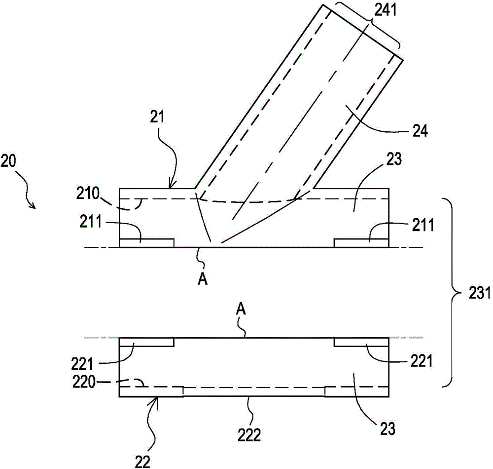
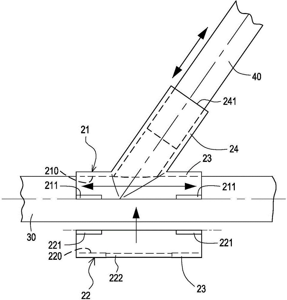
[0038] Such as figure 2 The illustrated front exploded view of the heterogeneous pipe joint of the present invention is shown. The different-material pipe joint 20 in this embodiment includes an upper joint body 21 and a lower joint body 22 . The upper joint body 21 is made of a first metal material (such as steel), and the lower joint body 22 is made of a second metal material (such as aluminum alloy) different from the first metal material. The bottom of the upper joint body 21 is a groove body 210 with a concave surface, the top of the lower joint body 22 is a groove body 220 with a concave surface, the upper joint body 21 and the lower joint body 22, Butt up and down to jointly define a first pipe body 23 and first nozzles 231 at both ends of the first pipe body 23, the upper joint pipe body 21 and the lower joint pipe body 22 are respectively at their pre-join...


PUM


Abstract

The invention discloses a special tube part jointing structure, a jointing method and a special tube joint, which are used for the assembly of a space truss. The special tube joint comprises an upper joint tube body and a lower joint tube body, wherein the upper joint tube body is made of first metal materials, and the lower joint tube body is made of second metal materials different from the first metal materials. The upper and lower joint tube bodies are connected in a butting manner to form a first tube body. The external surfaces of the upper and lower joint tube bodies are respectively provided with a plurality of upper pole lugs and corresponding lower pole lugs in an outwards convex manner, wherein the upper and lower pole lugs can be stacked in a face-to face manner. A side, far from the first tube body, of the upper joint tube body stretches outwards to form a second tube body.

Description

technical field [0001] The present invention relates to a joint structure and method of dissimilar pipe fittings and joints of dissimilar pipe fittings, in particular to a joint structure and method of dissimilar pipe fittings applied to the assembly of space trusses of members of dissimilar metal materials and the joining method of dissimilar pipe fittings made of different materials. Assembled pipe fittings. Background technique [0002] At present, the trapezoidal frame composed of longitudinal beams and cross beams is mostly composed of I-shaped steel and channel steel. The load of the whole vehicle is borne by the frame to cause elastic deformation of the frame. The type body is easy to generate a large shear force on the frame, which is easy to cause the weld to break. In order to generate sufficient strength for this kind of building block frame structure, the overall frame is relatively heavy, which relatively compresses the loadable space. High fuel consumption and...

Claims


Application Information

Patent Timeline
Patent Type & Authority Applications(China)
IPC IPC(8): F16S3/08
Inventor 林志伦林典永
Owner METAL INDS RES & DEV CENT
Why Eureka
Try Eureka