Method for automatic collimation of cubic mirror based on machine vision

A technology of machine vision and cube mirror, which is applied to the interpretation of instruments, measuring instruments, and photos, etc., can solve the problems of not allowing, not being able to measure automatically, and not realizing the collimation and guiding function of the cube mirror, so as to reduce dependence and improve measurement efficiency and the effect of degree of automation

Inactive Publication Date: 2015-05-13
BEIJING INST OF SPACECRAFT ENVIRONMENT ENG
View PDF4 Cites 22 Cited by
  • Summary
  • Abstract
  • Description
  • Claims
  • Application Information

AI Technical Summary

Problems solved by technology

[0006] Both of the above two methods realize the identification and coordinate measurement of specific target points, but to apply them to the measurement of spacecraft cube mirrors, specific targets must be attached to the cube mirrors, which is not allowed in engineering
Moreover, the above method does not realize the collimation and guidance function of the cube mirror, and cannot perform automatic measurement of the mirror normal direction.

Method used


Image

  • Method for automatic collimation of cubic mirror based on machine vision
  • Method for automatic collimation of cubic mirror based on machine vision
  • Method for automatic collimation of cubic mirror based on machine vision

Examples


Embodiment Construction

[0021] The following introduces the specific implementation mode as the content of the present invention, and the content of the present invention will be further clarified through the specific implementation mode below. Of course, the following specific embodiments are described only to illustrate different aspects of the present invention, and should not be construed as limiting the scope of the present invention.

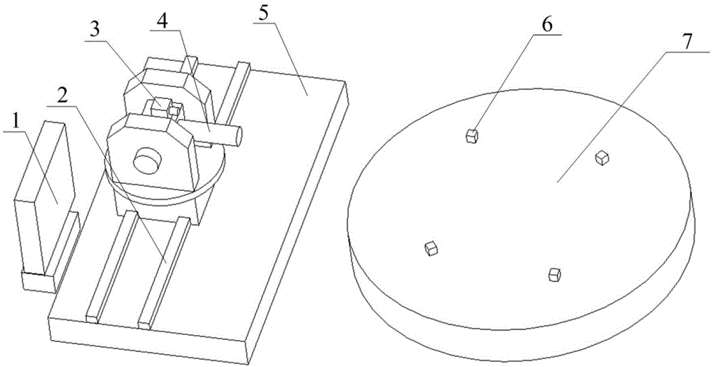
[0022] Such as figure 1 As shown, the automatic guidance system for cube mirror alignment measurement based on machine vision of the present invention includes: computer 1 for image processing and pose solution, precision guide rail 2, CCD camera 3, theodolite 4, motion control platform 5, waiting Measuring cube mirror 6 and high-precision turntable 7. Utilize camera 3 to carry out the pose measurement of cubic mirror 6 and realize the automatic guidance to the theodolite, mainly comprise the following steps:

[0023] (1) Installation between camera 3 and theod...


PUM


Abstract

The invention discloses an automatic guide method for collimation measurement of a cubic mirror based on machine vision. The method comprises the following steps: rotating an industrial camera together with a theodolite, keeping the relative position relationship unchanged, controlling the camera to collect an image of a cubic mirror to be measured, identifying the cubic mirror by image processing, extracting corner points of the cubic mirror, and obtaining the coordinate values of the corner points under an image coordinate system; establishing a mathematical model of a camera coordinate system, a cubic mirror coordinate system and a theodolite coordinate system, performing coordinate transformation and calculating the position of an intersection of a normal line of a mirror surface to be measured of the cubic mirror and a movement plane of the theodolite under the mathematical model, controlling the theodolite to move to the position of the intersection, and adjusting the posture of the theodolite according to the normal direction of the mirror surface to be measured of the cubic mirror, so that the normal direction of the mirror surface to be measured of the cubic mirror moves into the range of field of view of the theodolite, and the automatic collimation of the cubic mirror is implemented on the basis of the automatic theodolite collimation step for image identification.

Description

technical field [0001] The invention belongs to the technical field of spacecraft assembly measurement, and in particular relates to measuring the position and attitude of a cube mirror by using machine vision, and then guiding theodolite to move to a corresponding position based on the position and attitude of the cube mirror obtained by machine vision measurement, and adjusting the angle of the theodolite, Realize the automatic collimation of the theodolite to the cube mirror. Background technique [0002] Accuracy measurement is an important guarantee for the reliable operation of spacecraft. In order to ensure the normal operation of the spacecraft, it is necessary to measure the geometric accuracy of its structural shape and precision-required instruments and equipment during ground assembly, such as the earth sensor on the spacecraft, Attitude-sensitive instruments such as sun and star sensors and inertial devices; power components such as 10N thrusters and 490N engine...

Claims


Application Information

Patent Timeline
Patent Type & Authority Applications(China)
IPC IPC(8): G01C1/04G01C15/00
CPCG01C1/04G01C11/02G01C11/10G01C15/00
Inventor 刘涛杨再华闫荣鑫胡瑞钦易旺民万毕乐郭洁瑛于兆吉王伟刘浩淼阮国伟陶力
Owner BEIJING INST OF SPACECRAFT ENVIRONMENT ENG
Why Eureka
Try Eureka