Method and equipment for shortening charging time
A technology that shortens charging time and equipment. It is used in secondary battery charging/discharging, current collectors, electric vehicles, etc., and can solve the problems of insufficient charging time and shortening.
- Summary
- Abstract
- Description
- Claims
- Application Information
AI Technical Summary
Problems solved by technology
Method used
Image

Examples
Embodiment Construction
[0016] In order to make the technical problems, technical solutions and beneficial effects to be solved by the present invention clearer, the present invention will be further described in detail below in conjunction with the accompanying drawings and embodiments. It should be understood that the specific embodiments described here are only used to explain the present invention, not to limit the present invention.
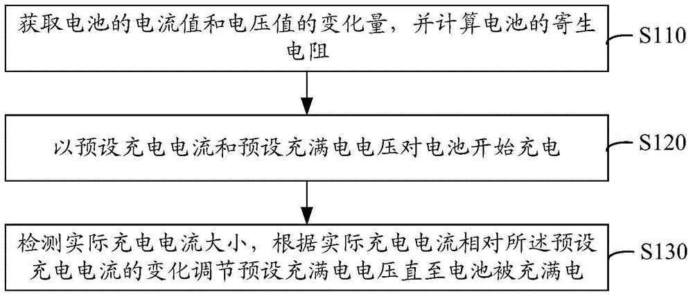
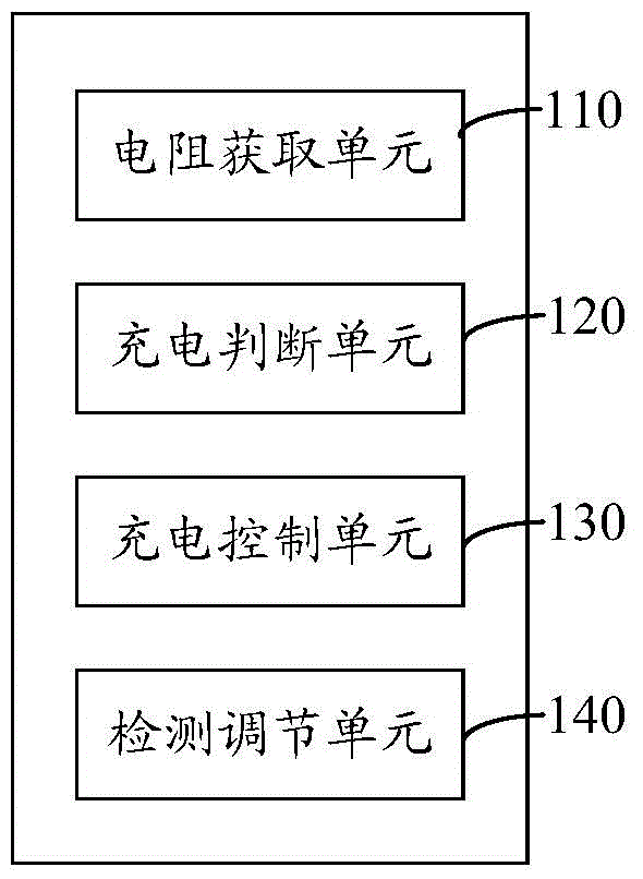
[0017] see figure 1 and figure 2 , the method for shortening the charging time in a preferred embodiment of the present invention is applied to a portable electronic device including a rechargeable battery, such as a mobile terminal, and the method includes the following steps:
[0018] Step S110, acquiring the variation of the current value and the voltage value of the battery, and calculating the parasitic resistance of the battery. The voltage of the battery and the data of charging and discharging current can be obtained at any time through a device, such as...
PUM
 Abstract
Description
Claims
Application Information
 - Generate Ideas
- Intellectual Property
- Life Sciences
- Materials
- Tech Scout
- Unparalleled Data Quality
- Higher Quality Content
- 60% Fewer Hallucinations
Browse by: Latest US Patents, China's latest patents, Technical Efficacy Thesaurus, Application Domain, Technology Topic, Popular Technical Reports.
© 2025 PatSnap. All rights reserved.Legal|Privacy policy|Modern Slavery Act Transparency Statement|Sitemap|About US| Contact US: help@patsnap.com