Permanent magnet crossed type axial magnetic field magnetic flow switching type memory motor

An axial magnetic field, magnetic flux switching technology, applied in the magnetic circuit shape/style/structure, synchronous machine, electrical components and other directions, can solve the problems of poor torque performance, large weak field loss, large cogging torque, etc. Achieving the effect of large and constant power operating range, low magnetic field loss and high power density

Active Publication Date: 2015-05-13
SOUTHEAST UNIV
View PDF6 Cites 9 Cited by
  • Summary
  • Abstract
  • Description
  • Claims
  • Application Information

AI Technical Summary

Problems solved by technology

The double salient pole structure of the traditional flux switching motor makes the cogging torque larger and the torque performance is poor
The flux switching motor adopts the stator permanent magnet structure. As a permanent magnet motor, there is also the problem that the air gap magnetic field is difficult to adjust.
When the motor is running at low speed and low torque, the iron consumption of the motor is large; when the motor is running at high speed, the traditional method uses direct-axis demagnetization current or a separate field-weakening winding to maintain the field-weakening operation, just like other types of permanent magnet motors , there is a problem of large weak magnetic loss

Method used


Image

  • Permanent magnet crossed type axial magnetic field magnetic flow switching type memory motor
  • Permanent magnet crossed type axial magnetic field magnetic flow switching type memory motor
  • Permanent magnet crossed type axial magnetic field magnetic flow switching type memory motor

Examples


Embodiment Construction

[0017] The present invention will be further explained below in conjunction with the drawings.

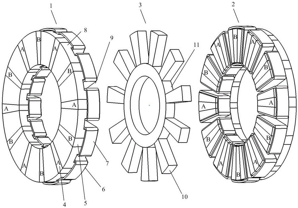
[0018] Such as figure 1 Shown is a 12 / 11 pole permanent magnet interleaved axial magnetic field flux switching type memory motor, including two salient pole structure stators and a salient pole structure rotor 3. The two stators have the same structure and are respectively marked as the first The stator 1 and the second stator 2 are arranged in opposite positions, and the rotor 3 is arranged coaxially between the two stators.

[0019] The stator on one side includes 12 U-shaped conductive cores 8, 12 U-shaped conductive cores 8 are evenly arranged to form a circular ring shape, the opening of the U-shaped conductive core 8 faces the rotor 3, and two adjacent U-shaped conductive cores There is a gap between the cores 6; the high coercive force permanent magnet A4 and the low coercive force permanent magnet B5 are embedded in the gap along the circumferential direction, and the low coerci...


PUM


Abstract

The invention discloses a permanent magnet crossed type axial magnetic field magnetic flow switching type memory motor. The permanent magnet crossed type axial magnetic field magnetic flow switching type memory motor comprises two stators with convex pole structures and a rotor with a convex pole structure, wherein the structures of the two stators are the same and the two stators are marked into a first stator and a second stator respectively; the positions of the stators are opposite; the rotor is coaxially arranged between the two stators; each stator comprises a U-shaped magnetism-conductive iron core, a permanent magnet, a three-phase armature winding and a direct-current magnetizing winding; the permanent magnets comprises a high coercivity permanent magnet A and a low coercivity permanent magnet B; the iron cores and the permanent magnets are peripherally and alternatively arranged to form a circular ring shape; the two permanent magnets are alternatively arranged, and the magnetizing directions of the adjacent permanent magnets are opposite; the magnetizing directions of the permanent magnets on the corresponding positions of the two stators are opposite; columnar rotor teeth are uniformly arranged on a non-magnetism-conductive annular rotary shaft along the peripheral direction. The memory motor adopts a mixed permanent magnet excitation manner and has higher torque density; the flux weakening is carried out through adjusting the magnetizing level of the low coercivity permanent magnet, and the flux weakening capability and constant-power operation efficiency of the memory motor are improved.

Description

Technical field [0001] The invention relates to a permanent magnet interleaved axial magnetic flux switching type memory motor. Background technique [0002] Permanent magnet synchronous motors have been widely used in industry, aerospace and other fields due to their advantages of high power density, high efficiency, and simple structure. However, due to the limitation of the characteristics of the permanent magnet material, the traditional permanent magnet motor has the problems that the air gap magnetic field is difficult to adjust, and it is difficult to achieve a wide speed range. With the development of permanent magnet materials and permanent magnet motors, more and more household appliances and electric vehicles are driven by permanent magnet motors. The motors in these devices need to run at variable speeds. When running at low speeds and low torques, they consume more iron. In high-speed operation, due to the inverter voltage limitation, field weakening control is gene...

Claims


Application Information

Patent Timeline
Patent Type & Authority Applications(China)
IPC IPC(8): H02K16/04H02K1/17H02K1/22
CPCH02K1/17H02K1/24H02K21/029H02K2213/03
Inventor 林明耀李念郝立徐妲付兴贺
Owner SOUTHEAST UNIV
Why Eureka
Try Eureka