Optical link linearization method

A routed, optical link technology, applied in the field of optical communication, can solve problems such as solution failure, increase the complexity and difficulty of experimental operation, achieve the effect of simple design, reduce the complexity of experimental operation, and increase system stability

Active Publication Date: 2015-05-13
BEIJING UNIV OF POSTS & TELECOMM
View PDF10 Cites 4 Cited by
  • Summary
  • Abstract
  • Description
  • Claims
  • Application Information

AI Technical Summary

Problems solved by technology

At the same time, there will be a very strict synchronization problem between the distorted signal and the compensated signal. Any phase offset may lead to the failure of the scheme, which increases the complexity and difficulty of the experimental operation.

Method used


Image

  • Optical link linearization method
  • Optical link linearization method
  • Optical link linearization method

Examples


Embodiment Construction

[0054] In order to make the purpose, technical solutions and advantages of the embodiments of the present invention clearer, the technical solutions in the embodiments of the present invention will be clearly described below in conjunction with the accompanying drawings in the embodiments of the present invention. Obviously, the described embodiments are the Some, but not all, embodiments are invented. Based on the embodiments of the present invention, all other embodiments obtained by persons of ordinary skill in the art without making creative efforts belong to the protection scope of the present invention.

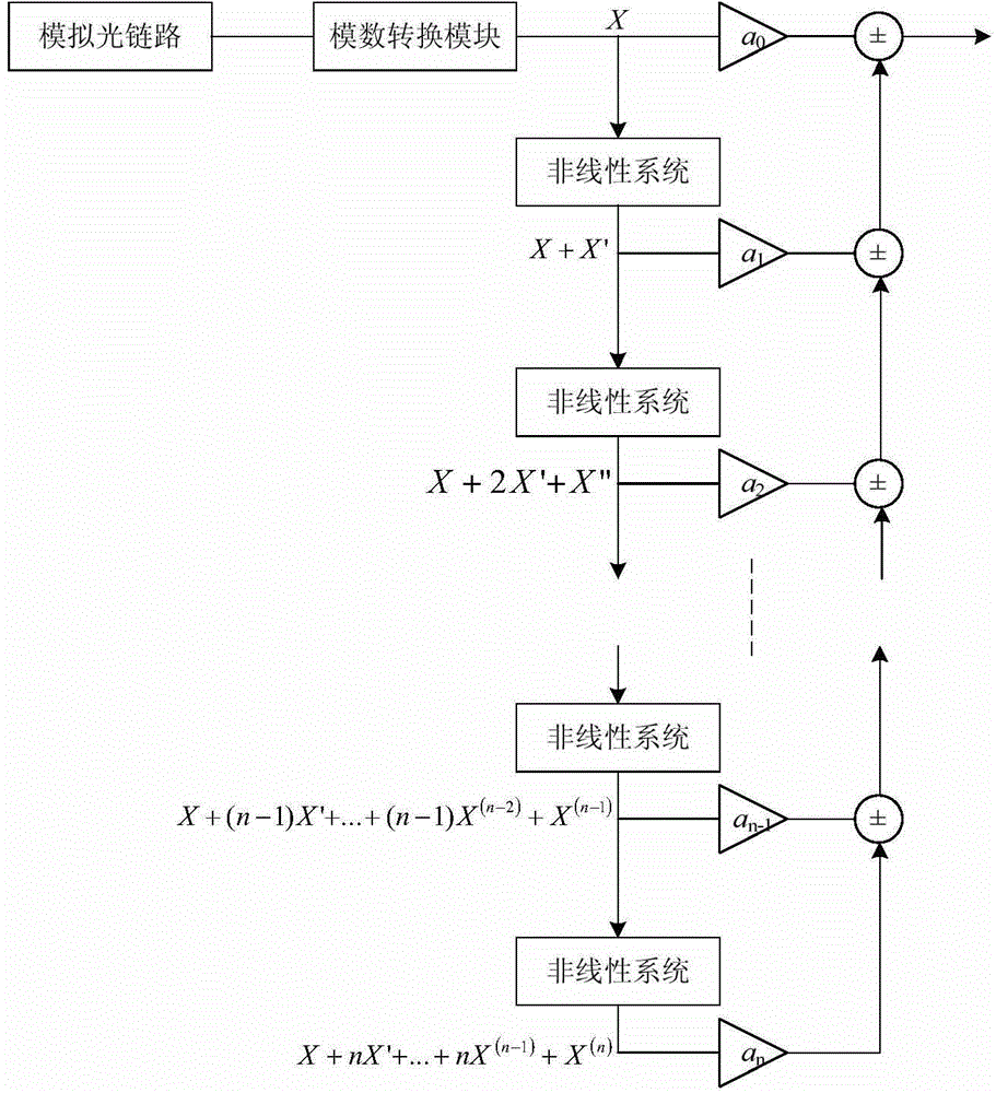
[0055] Such as Figure 4 As shown, this embodiment discloses a method for optical link linearization, the method comprising:

[0056] S1. Obtain an optical signal from an optical link, and detect and restore a distorted electrical signal from the optical signal;

[0057] S2. Construct a compensation signal according to the distorted electrical signal;

[0058] S3. Co...


PUM


Abstract

The invention discloses an optical link linearization method. The optical link linearization method comprises step 1, obtaining an optical signal from an optical link and detecting and recovering a distorted electrical signal from the optical signal; step 2, building a compensation signal according to the distorted electrical signal; step 3, performing compensation on the distorted electrical signal through the compensation signal so as to enable the optical link to be linearized. According to the optical link linearization method, the optical link is an incoherent intensity modulation direct detection link and the simultaneous inhibition of IMD3 (Third-order Intermodulation Distortion) and XMD (Cross-over Modulation Distortion) is implemented by an optical down-conversion and digital post-processing combined nonlinear compensation algorithm; the operation complexity of the existing coherent detection technology experiment is reduced and the system stability is increased; meanwhile the accurate estimation on link parameters or the careful construction on a compensation light path when nonlinear compensation signals are established in a digital domain in the existing technical scheme is avoided and the implementation difficulty of the existing nonlinear inhibition algorithm is simplified.

Description

technical field [0001] The invention relates to the technical field of optical communication, in particular to an optical link linearization method. Background technique [0002] The analog optical link has significant advantages such as low power consumption, high bandwidth, and anti-electromagnetic interference. It has emerged in the research of generating, distributing, controlling, and processing radio frequency signals, and has been actively explored by researchers at home and abroad. Photon technology has inherent and unique advantages in processing ultra-wideband, high-frequency and multi-carrier signals. However, most analog optical links inevitably include electrical-optical conversion and optical-electrical conversion modules, and the resulting nonlinearity seriously limits the performance of the link. Harmonic Distortion (HD) and carrier in-band intermodulation distortion (third-order Intermodulation Distortion, IMD3) ) and inter-carrier intermodulation distorti...

Claims


Application Information

Patent Timeline
Patent Type & Authority Applications(China)
IPC IPC(8): H04B10/2507H04L25/49H04L27/38
Inventor 戴一堂徐坤梁晓东尹飞飞李建强
Owner BEIJING UNIV OF POSTS & TELECOMM
Why Eureka
Try Eureka