A symbol synchronization method and device for a wireless communication test system

A symbol synchronization and testing system technology, applied in the field of communication, can solve the problem of the large amount of computation of the symbol synchronization method, and achieve the effect of reducing the difficulty of implementation, reducing the complexity, and improving the synchronization accuracy.

Active Publication Date: 2018-05-08
THE 41ST INST OF CHINA ELECTRONICS TECH GRP
View PDF6 Cites 0 Cited by
  • Summary
  • Abstract
  • Description
  • Claims
  • Application Information

AI Technical Summary

Problems solved by technology

[0005] Aiming at the problem of relatively large amount of computation in the symbol synchronization method in the related art, the present invention provides a symbol synchronization method and device for a wireless communication test system to solve the above technical problems

Method used


Image

  • A symbol synchronization method and device for a wireless communication test system
  • A symbol synchronization method and device for a wireless communication test system
  • A symbol synchronization method and device for a wireless communication test system

Examples


Embodiment 1

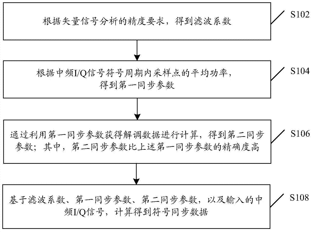
[0025] figure 1 Shown is the flow chart of the symbol synchronization method of the wireless communication test system, as figure 1 shown, including:

[0026] In step S102, filter coefficients are obtained according to the accuracy requirements of the vector signal analysis.

[0027] In step S104, a first synchronization parameter is obtained according to the average power of the sampling points within the symbol period of the intermediate frequency I / Q signal.

[0028] The specific process is: according to the average power of the sampling point in the symbol period of the above-mentioned intermediate frequency I / Q signal, the symbol synchronization position is estimated; based on the above-mentioned symbol synchronization position, the first synchronization parameter is obtained;

[0029] In step S106, the second synchronization parameter is obtained by using the first synchronization parameter to obtain demodulated data for calculation; wherein, the accuracy of the second...

Embodiment 2

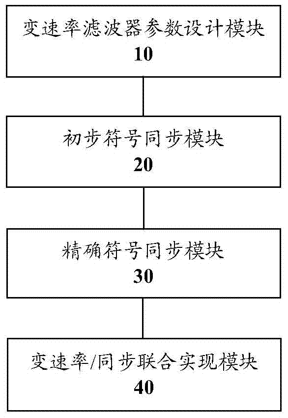
[0035] figure 2 Shown is the structural block diagram of the symbol synchronization device of the wireless communication test system, such as figure 2 shown, including:

[0036] The variable rate filter parameter design module 10 is connected to the variable rate / synchronization joint realization module 40, and is used to obtain filter coefficients according to the accuracy requirement of vector signal analysis.

[0037] The preliminary symbol synchronization module 20 is connected to the variable rate / synchronization joint implementation module 40, and is used to obtain the first synchronization parameter according to the average power of the sampling points in the symbol period of the intermediate frequency I / Q signal.

[0038] Specifically, it is also used for: estimating and obtaining the symbol synchronization position according to the average power of the sampling point in the symbol period of the intermediate frequency I / Q signal; and obtaining the first synchronizat...

Embodiment 3

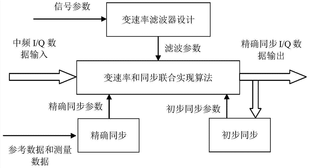
[0046] image 3 Shown is a schematic diagram of the operation flow of the symbol synchronization device, such as image 3 As shown, the symbol synchronization device includes four modules: variable rate filter parameter design module, preliminary symbol synchronization module, precise symbol synchronization module and variable rate / synchronization joint realization module. in,

[0047] The variable rate filter parameter design module designs filter coefficients and outputs them to the variable rate / synchronous joint realization module;

[0048] The preliminary symbol synchronization module estimates the symbol synchronization preliminary position, and obtains the preliminary synchronization parameter (ie, the above-mentioned first synchronization parameter) based on the symbol synchronization preliminary position, and outputs it to the variable rate / synchronization joint realization module;

[0049] The precise symbol synchronization module estimates the precise symbol synch...


PUM


Abstract

The invention discloses a symbol synchronization method and device of a wireless communication test system. Wherein the method includes: obtaining the filter coefficient according to the accuracy requirement of the vector signal analysis; obtaining the first synchronization parameter according to the average power of the sampling point in the symbol period of the intermediate frequency I / Q signal; obtaining the demodulation data by using the first synchronization parameter for calculation , to obtain the second synchronization parameter; wherein, the accuracy of the second synchronization parameter is higher than that of the first synchronization parameter; based on the filter coefficient, the first synchronization parameter, the second synchronization parameter, and the input intermediate frequency I / Q signal, the symbol synchronization is calculated data. Through the present invention, the problem of relatively large amount of calculation in the symbol synchronization method in the related art is solved, and the requirements of the wireless communication test system and the electronic measuring instrument are met; the known setting parameters in the vector signal analysis and the measurement parameters obtained after the measurement are used , reduce the complexity of the synchronization estimation algorithm, adopt two-level symbol synchronization, and improve the synchronization precision of the digital realization.

Description

technical field [0001] The invention relates to the communication field, in particular to a symbol synchronization method and device for a wireless communication testing system. Background technique [0002] Modern wireless communication networks adopt digital modulation and demodulation technology, which effectively overcomes various adverse effects brought by wireless channels, and improves the utilization rate of spectrum resources. It has become the basic form of modern radio frequency / microwave communication, and has driven the research of new testing technologies. . Vector signal analysis technology is one of the key test technologies for wireless communication testing. It has accurate and intuitive modulation parameter measurement capabilities and is widely used in vector signal analysis instruments and wireless communication measurement systems. [0003] Symbol synchronization (or timing recovery) is one of the most critical techniques in vector signal analysis tech...

Claims


Application Information

Patent Timeline
Patent Type & Authority Patents(China)
IPC IPC(8): H04L27/26
Inventor 徐兰天凌云志周建烨
Owner THE 41ST INST OF CHINA ELECTRONICS TECH GRP
Why Eureka
Try Eureka