Self-regulating gas generator and method

A gas generating device and self-regulating technology, which is applied in the direction of gas generating devices, chemical instruments and methods, electrochemical generators, etc., can solve the problems of unfriendly environment and pollution, and achieve the effect of long catalyst life

Inactive Publication Date: 2015-05-13
ENCITE LLC
View PDF7 Cites 7 Cited by
  • Summary
  • Abstract
  • Description
  • Claims
  • Application Information

AI Technical Summary

Problems solved by technology

One such disadvantage is a form of pollution where AC power plants, gas generators, and batteries each produce environmentally unfriendly by-products (such as ozone-destroying gases and battery acid waste)

Method used


Image

  • Self-regulating gas generator and method
  • Self-regulating gas generator and method
  • Self-regulating gas generator and method

Examples


Embodiment Construction

[0044] Preferred embodiments of the present invention are described below.

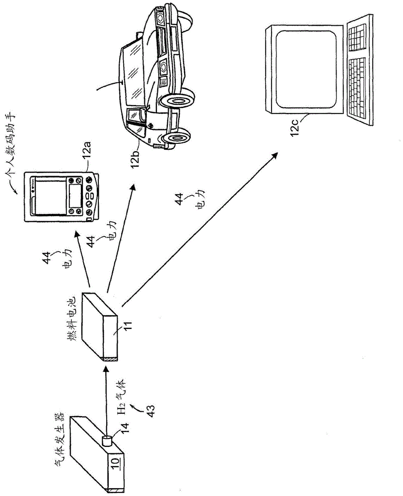
[0045] figure 1 is an illustration of a fuel cell application in which a gas generator 10 in accordance with the principles of the present invention may be used. In fuel cell applications, the gas generator 10 generates hydrogen gas and releases it to the fuel cell 11 . The fuel cell 11 reacts hydrogen and oxygen to generate electricity 44, as is known in the art. The fuel cell 11 provides power 44 for power consuming devices such as personal entertainment devices 12a (eg MP3 players), remote controlled cars 12b or portable computers. Other fuel cell applications include military electronics, industrial electronics (such as printing presses), or consumer electronics (such as mobile phones, personal digital assistants (PDAs), etc.).

[0046] Typically, a fuel cell consumes hydrogen at a rate based on how much it generates. An example of a fuel cell is described in US Patent No. 6,312,846, issued No...


PUM


Abstract

A self-regulating gas generator that, in response to gas demand, supplies and automatically adjusts the amount of gas (e.g., hydrogen or oxygen) catalytically generated in a chemical supply chamber from an appropriate chemical supply, such as a chemical solution, gas dissolved in liquid, or mixture. In some embodiments, the gas generator may employ a piston, rotating rod, or other element(s) to expose the chemical supply to the catalyst in controlled amounts. In another embodiment, the self-regulating gas generator uses bang-bang control, with the element(s) exposing a catalyst, contained within the chemical supply chamber, to the chemical supply in ON and OFF states according to a self-adjusting duty cycle, thereby generating and outputting the gas in an orientation-independent manner. The gas generator may be used to provide gas for various gas consuming devices, such as a fuel cell, torch, or oxygen respiratory devices.

Description

[0001] related application [0002] This application is a continuation of U.S. Application No. 13 / 465,798, filed May 7, 2012, and a continuation of U.S. Application No. 13 / 464,881, filed May 4, 2012, U.S. Application No. 13 / 464,881 is a continuation-in-part of U.S. Application No. 10 / 989,116 (now U.S. Patent No. 8,172,912), filed November 15, 2004, which claims U.S. provisional application filed November 14, 2003 Priority of No. 60 / 520,149. The entire teachings of the aforementioned applications are hereby incorporated by reference. Background of the invention [0003] Today, nearly all military, industrial, and consumer electronic devices are powered by conventional power sources (AC wall outlets, gas generators, or disposable or rechargeable batteries). Each of these power supplies has its own disadvantages. One such disadvantage is a form of pollution in which AC power plants, gas generators, and batteries each produce environmentally unfriendly by-products (eg, ozone-de...

Claims


Application Information

Patent Timeline
Patent Type & Authority Applications(China)
IPC IPC(8): B01J19/18B01J23/40B01J7/02C01B3/06F17C11/00H01M8/06H01M8/04
CPCB01J7/02B01J19/1893C01B3/065C01B3/501F17C11/005H01M8/04208H01M8/04216H01M8/0606H01M8/0687B01J2219/185B01J2219/00182B01J2219/00162B01J2219/00186Y02E60/32Y02E60/36Y02E60/50
Inventor S.A.马什D.M.帕克P.N.平陶罗
Owner ENCITE LLC
Why Eureka
Try Eureka