Yoke for universal joint and production method therefor

A technology of universal joints and manufacturing methods, which is applied in the direction of manufacturing tools, engine components, and assembly of parts into assemblies, etc., which can solve the problems of difficulty in strength design and achieve the effect of easy strength and rigidity

Active Publication Date: 2015-05-13
NSK LTD
View PDF11 Cites 4 Cited by
  • Summary
  • Abstract
  • Description
  • Claims
  • Application Information

AI Technical Summary

Problems solved by technology

Therefore, in order to ensure the strength o

Method used


Image

  • Yoke for universal joint and production method therefor
  • Yoke for universal joint and production method therefor
  • Yoke for universal joint and production method therefor

Examples


Embodiment Construction

[0063] (First example of implementation)

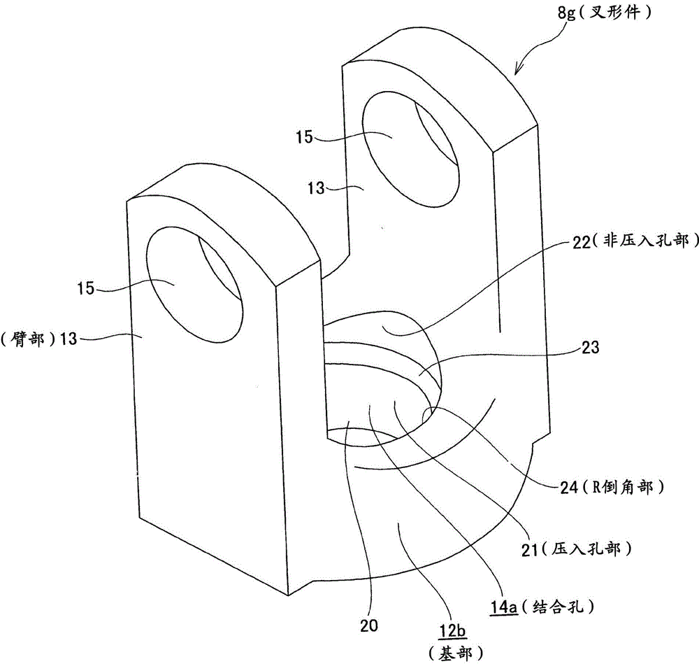
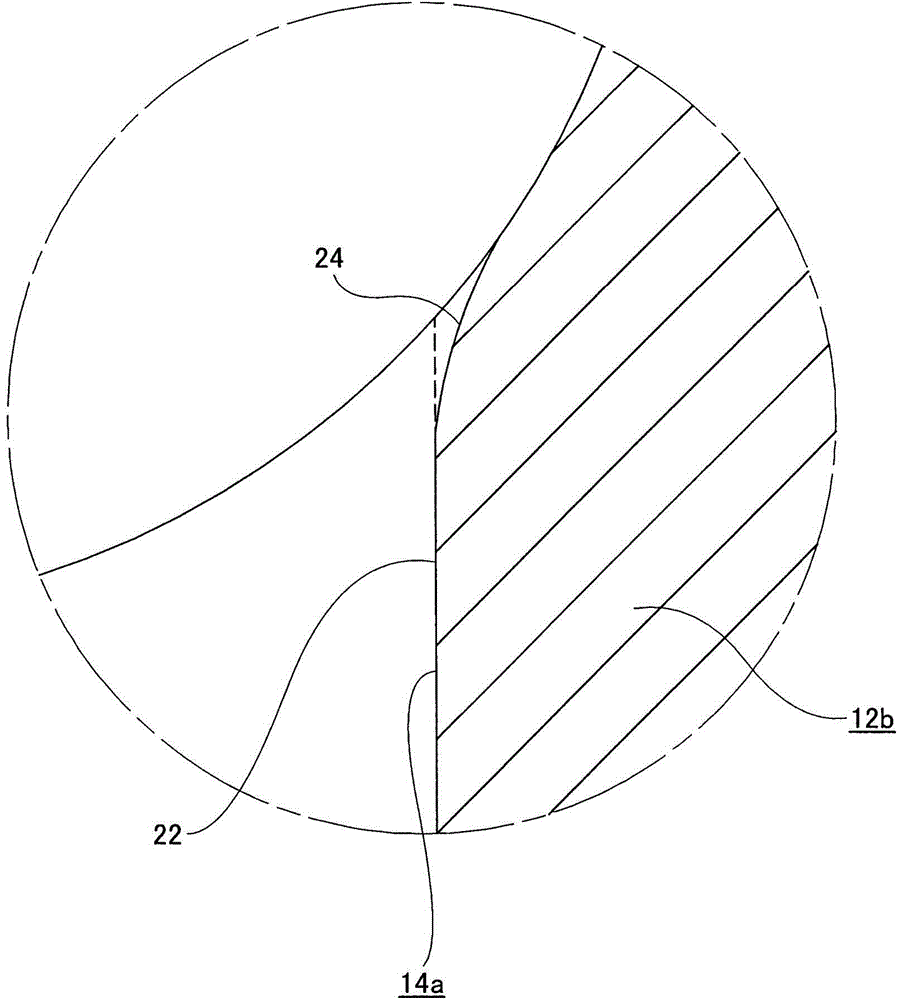
[0064] Figure 1 ~ Figure 7 The first example of the embodiment of the present invention is shown. The features of this example are mainly the structure of the coupling hole 14a provided in the radial center portion of the base portion 12b, and the manufacturing method of the fork 8g provided with such coupling hole 14a. Including the aspect that the central portion of the other side surface of the base portion 12b in the axial direction is provided with the projecting ring portion 20 that can improve the welding strength, the structure and function of the other portions are the same as those described above. Figure 14 The second example of the conventional structure shown is the same, so that repeated descriptions are omitted or are briefly described. Hereinafter, the description will focus on the characteristic parts of this example. In the following description, in the axial direction of the fork 8g (and its intermediate material), o...


PUM


Abstract

A yoke for a universal joint, having provided in a coupling hole (14a): a press-fit hole section (21) for press-fitting an end section of a shaft, provided between a center section and another end section in the axial direction; and a non-press-fit hole section (22) having a larger diameter than the press-fit hole section (21) and not having the shaft end section press-fitted therein, provided at one end section in the axial direction.

Description

Technical field [0001] The present invention relates to an improvement in a fork that constitutes a cross-shaft universal joint (universal joint) and a method for manufacturing the same. The cross-shaft universal joint is used to connect rotating shafts constituting a steering device to each other so as to be able to transmit rotation. Moment. Background technique [0002] The steering device of the car such as Picture 11 Structure as shown. The operation of the steering wheel 1 operated by the driver is transmitted to the input shaft 6 of the steering gear unit 5 via the steering shaft 2, the universal joint 3a, the intermediate shaft 4, and the other universal joint 3b. The rack and pinion mechanism built into the steering gear unit 5 is configured to push and pull the pair of left and right tie rods 7 and 7 to provide the pair of left and right steering wheels with an appropriate steering angle corresponding to the amount of operation of the steering wheel 1. [0003] As unive...

Claims


Application Information

Patent Timeline
IPC IPC(8): F16D3/26B21K1/14
CPCB21J5/02B21K1/765B21K25/00F16D1/068F16D1/0858F16D3/387
Inventor 仲村拓真黑川祥史
Owner NSK LTD
Why Eureka
Try Eureka