
A surface depth measuring device

A technology for measuring device and surface depth, which is applied in the direction of measuring device, optical device, diagnostic recording/measurement, etc. It can solve the problems of affecting measurement accuracy, slow measurement, high environmental requirements, etc., and achieve high measurement accuracy, convenient operation and simple operation Effect

Active Publication Date: 2016-11-23
广州中广测计量检测技术有限公司
View PDF8 Cites 0 Cited by
  • Summary
  • Abstract
  • Description
  • Claims
  • Application Information

AI Technical Summary

Problems solved by technology

At present, the measuring instruments in the depth direction of the sample surface include stylus instruments, stereo microscopes, traditional interferometers, etc. The stylus instruments need to be in contact with the object to be measured, which may easily cause damage to the measurement object and affect the measurement accuracy. Stereo microscopes require The microscopic measurement of the cross-section after dissecting the object to be measured belongs to contact or destructive measurement
The traditional interferometer calculates the depth value by observing the change of the interference fringe, which has high requirements on the environment and is very inconvenient when observing the movement of the fringe
In the process of laser surgery on the living body, the contact measurement is slow, the accuracy is not high, and the operation is inconvenient; the method of in vivo biological slices is used to cut the sample tissue longitudinally for measurement, and it is impossible to measure the living body, especially in the medical field. The correct objects are all patients, and the measurement method should be non-contact, non-destructive and fast

Method used


Image

  • A surface depth measuring device
  • A surface depth measuring device
  • A surface depth measuring device

Examples


Embodiment

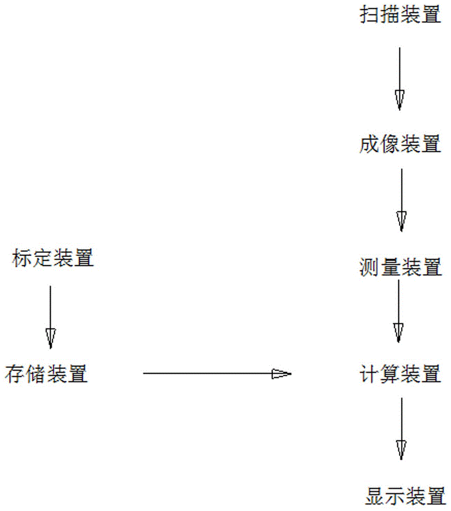
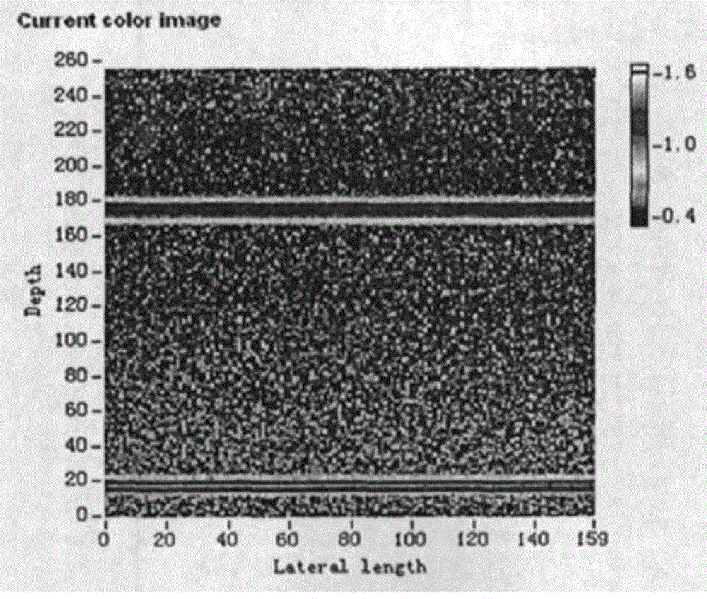
[0022] refer to figure 1 , the data of the calibration device is output to the storage device and saved for later use; after the data of the scanning device is processed into a pseudo-color map by the imaging device, the length of the surface depth of the object on the pseudo-color map is measured by the measuring device, and the measurement result is output To the computing device, the computing device retrieves the calibrated data in the storage device, combines the data of the measuring device to calculate the actual depth of the object to be measured, and outputs it to the display device for display.

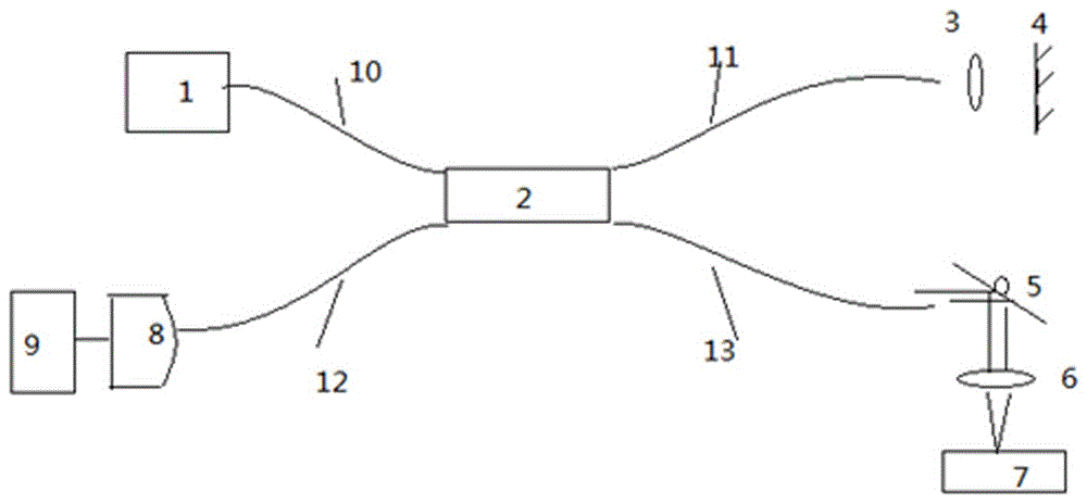
[0023] Please refer to figure 2 , the low-coherence fiber-optic Michelson interferometer constitutes the scanning device of the present invention, the light emitted by the light source 1 of the interferometer is divided into two beams of reference arm light and sample arm light through the fiber coupler 2, wherein the reference arm beam passes through the lens 3 and reflect...


PUM


Abstract

The invention discloses a surface depth measuring device comprising a scanning device, an imaging device, a display device, a calibrating device, a storing device, a measuring device and a calculating device, wherein the scanning device is used for scanning the to-be-measured surface depth of an object; the imaging device is used for processing data measured by the scanning device to form an image; the display device is used for outputting the to-be-measured surface depth of the object; the calibrating device is used for calibrating an in-air optical path represented by a unit pixel point on the scanned image; the storing device is used for storing an in-air unit optical path represented by a unit pixel point on the scanned image; the measuring device is used for measuring the pixel value of the to-be-measured surface depth of the object in the scanned image; and the calculating device is used for calculating the to-be-measured surface depth of the object. The surface depth measuring device has the beneficial effects of no need of direct contact, no damage, high speed, convenience in operation and high measuring precision.

Description

technical field [0001] The invention relates to the field of depth measurement, in particular to a surface depth measurement device. Background technique [0002] In many fields such as materials and manufacturing, the flatness of the material surface is an important factor in its performance. In laser surgery, the operator hopes to obtain real-time information on the laser parameters of a certain parameter (power, pulse width, pulse number, etc.) The ablation depth of a specific biological tissue. At present, the measuring instruments in the depth direction of the sample surface include stylus instruments, stereo microscopes, traditional interferometers, etc. The stylus instruments need to be in contact with the object to be measured, which may easily cause damage to the measurement object and affect the measurement accuracy. Stereo microscopes require The microscopic measurement of the cross-section after dissecting the object to be measured belongs to contact or destruct...

Claims


Application Information

Patent Timeline
Patent Type & Authority Patents(China)
IPC IPC(8): A61B5/107
CPCA61B5/1075A61B5/1079G01B11/22
Inventor 陈霞
Owner 广州中广测计量检测技术有限公司
Learn More