Wear protection assembly for an agitator mill

An agitated ball milling, anti-wear technology, applied in grain processing and other directions, can solve the problem of insufficient wear protection, achieve good dimensional deviation, prevent contact, and reduce the risk of failure

Active Publication Date: 2015-05-20
NETZSCH精细研磨技术有限公司
View PDF7 Cites 2 Cited by
  • Summary
  • Abstract
  • Description
  • Claims
  • Application Information

AI Technical Summary

Problems solved by technology

However, known solutions of the above-mentioned type do not adequately achieve this wear protection

Method used


Image

  • Wear protection assembly for an agitator mill
  • Wear protection assembly for an agitator mill
  • Wear protection assembly for an agitator mill

Examples


Embodiment Construction

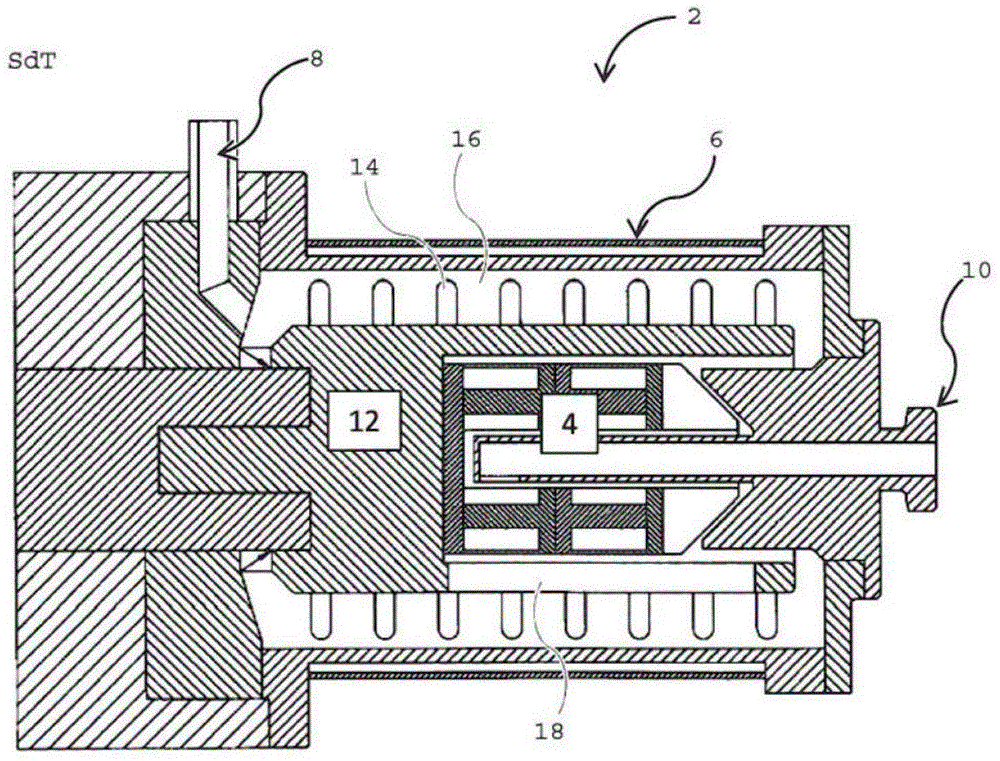
[0061] figure 1 The configuration of a known agitator ball mill 2 with a separating device 4 is shown schematically. The shown agitator ball mill 2 comprises a milling vessel 6 provided with a milling substance inlet 8 and a milling substance outlet 10 . A stirrer in the form of a stirrer shaft 12 is arranged centrally in the grinding container 6 . The stirring shaft 12 is provided with pin-shaped stirring bodies 14 which protrude into the grinding space 16 . The separating device 4 is provided inside the stirring shaft 12 . During operation of the grinder 2 , the medium to be ground is fed through the grinding material inlet 8 and conveyed in the direction of the grinding material outlet 10 . A grinding aid (not shown) is located in the grinding space 16 between the stirring shaft 12 and the grinding container 6 . The grinding substance-grinding auxiliary body-mixture is separated in the end region of the grinder 2 by means of the separating device 4, so that only the gri...


PUM


Abstract

A wear protection assembly for an agitator mill, in particular a stirred ball mill (2) is provided. The wear protection assembly comprises an agitator (12) provided with a module body (20), is intended to allow an effective protection against wear of the entire modular agitator (12). According to the invention, the module body (20) formed by a grinding disc (30) is arranged on the end side of at least one end portion of the agitator (12), and the module body (20) are axially clamped by a clamping device (32), wherein the clamping means (32) is provided with a protective body (38) serving as a cover and the module body (20), the clamping device (32) and the protective body (38) are equipped with sealing means (44).

Description

technical field [0001] The invention relates to a wear protection device for an agitator mill, in particular an agitator ball mill, having an agitator comprising a module body, and also to an agitator for an agitator ball mill. Background technique [0002] Agitator ball mills are used to comminute and homogenize solid particles, wherein the grinding aid is moved violently by means of an agitator, and the grinding aid consists, for example, of steel or a wear-resistant ceramic material. Here, solid particles are crushed by impact, pressure, scissors and friction. The grinding aids in the grinding container are activated by means of a stirrer which can be equipped with stirring bodies (eg rods or discs). [0003] The grinding aids used lead to wear, inter alia, of the grinding vessel and the stirrer. It has therefore been proposed in the past to equip the vessel walls with wear protection elements which can be replaced if necessary. For example, in the publication DE 10 20...

Claims


Application Information

Patent Timeline
Patent Type & Authority Applications(China)
IPC IPC(8): B02C17/20
CPCB02C17/20B02C17/163
Inventor H·默舍尔H·波许A·萨维尔瓦尔德L·P·韦兰
Owner NETZSCH精细研磨技术有限公司
Why Eureka
Try Eureka