
Vertical plate feeding numerical control drill with routing

A kind of engraving and milling and vertical technology, which is applied in the field of vertical board feeding CNC drilling, can solve the problems of difficult personalized product production, no engraving and milling, and inability to meet the requirements of workpiece appearance design, etc.

Active Publication Date: 2015-05-20
NANXING MACHINERY CO LTD
View PDF10 Cites 12 Cited by
  • Summary
  • Abstract
  • Description
  • Claims
  • Application Information

AI Technical Summary

Problems solved by technology

[0003] The existing equipment for drilling mortise holes has multiple rows of multi-spindle drill series. The disadvantage is that the axis base of the drilling shaft is fixed. After one adjustment, the machine is only suitable for drilling the same size of the plate. This equipment is used in mass production However, with the people's demand for product individuation, the shape and specification of the product are ever-changing, so the position of the bucket tenon also changes accordingly, and a very good personalized product is derived from it. The aforementioned wood drilling equipment is difficult to adapt to personalization product production
[0004] Later, some CNC drilling equipment appeared, which can be adjusted according to the drilling position of the workpiece, but there are still some defects and deficiencies, such as: (1) The plate is fed in a horizontal and horizontal direction, and its chip removal and dust suction Inconvenient, affecting the cleaning of the equipment; (2) During the processing process, the clamping mechanism needs to be moved multiple times to clamp the workpiece, which increases the difficulty of clamping and affects the machining accuracy of the workpiece; (3) The rigidity of the existing CNC drilling equipment Insufficient, the stability of the machine is not good, and the defective rate is high; (4) The CNC drill has fewer functions, no functions such as engraving and milling, sawing and grooving, and cannot meet the requirements of the workpiece appearance design (such as surface engraving and milling patterns, openings, etc.) slot, etc.)

Method used


Image

  • Vertical plate feeding numerical control drill with routing
  • Vertical plate feeding numerical control drill with routing
  • Vertical plate feeding numerical control drill with routing

Examples


Embodiment Construction

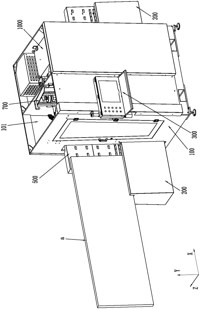
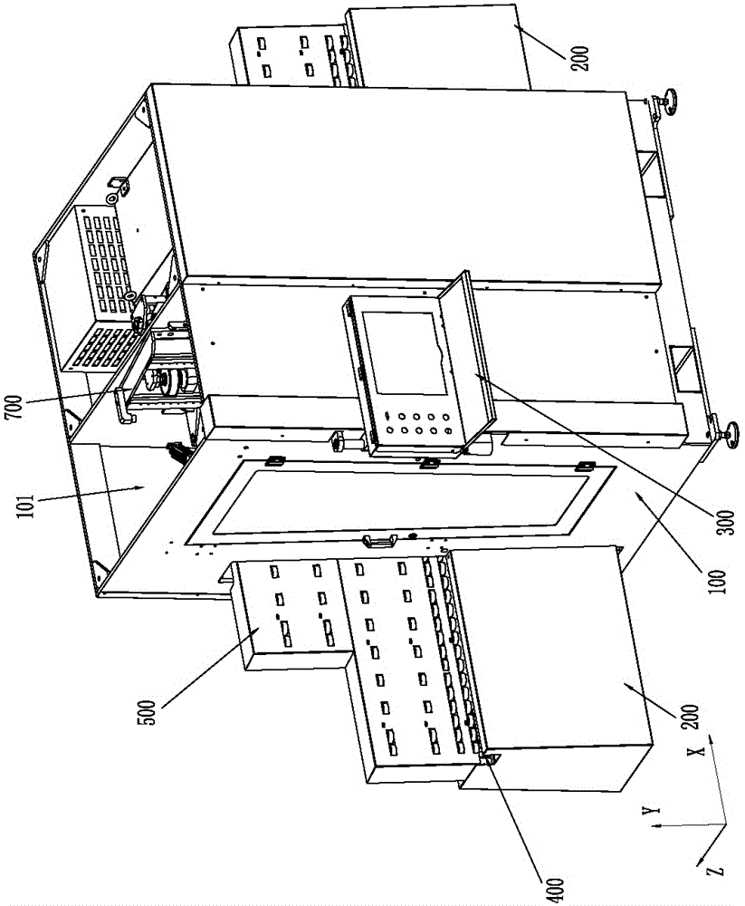
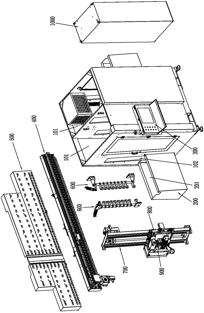
[0099] Please refer to Figure 1 to Figure 23 Shown, it has shown the concrete structure of the embodiment of the present invention;

[0100] The vertical plate feeding CNC drill with engraving and milling includes a frame part 100, an X-axis part 400, an inclined plate part 500, a pressing plate part 600, a Y-axis part 700, a Z-axis part 800, a drill box part 900, and an electric box part. 1000 and the operation panel part 300; wherein, the X-axis is arranged horizontally, the Y-axis is arranged vertically, and the Z-axis is arranged horizontally and respectively perpendicular to the X-axis and the Y-axis, such as Figure 1 to Figure 5 As shown, it is a vertical feeding of the plate a, and the drilling box part 900 is set as a horizontal type, that is, the drilling box and milling cutter are horizontally fed;

[0101] The frame part 100 includes a box body, a housing cavity 101 is formed in the box body, and a main channel 102 penetrating both sides of the box body along the...


PUM


Abstract

The invention discloses a vertical plate feeding numerical control drill with routing. The vertical plate feeding numerical control drill comprises a rack part, an X-axis part, a Y-axis part, a Z-axis part, a drill box part, an electric box part and an operation panel part, wherein the X-axis part comprises an X-axis transverse beam, a linear guide rail group, a mounting base plate, a gear, a rack, a clamp cylinder, a clamp fixing end, a clamp moving end and a first servo motor; the Y-axis part comprises a transverse beam, a Y-axis linear sliding rail, a second servo motor, a Y-axis lead screw and a Y-axis mounting plate; the Z-axis part comprises a Z-axis mounting plate, a first Z-axis slide block, a routing electric spindle, a Z-axis lead screw, a third servo motor and a fourth servo motor; and the drill box part is horizontally arranged on the Z-axis mounting plate and comprises a vertical drill, a left-right side drill, a top-bottom side drill and a grooving saw. Multifunctional full-numerical control machining is realized on a machine, the efficiency and machining precision are improved, the cost is saved, the drill is particularly suitable for machining individualized products, and the vertical plate feeding mode contributes to chip removal and dust collection.

Description

technical field [0001] The invention relates to the technology in the field of woodworking machinery, in particular to a vertical board-feeding numerical control drill with engraving and milling. Background technique [0002] Woodworking furniture and wood products materials include solid wood (logs) and man-made fiber boards, and the development of solid wood products is limited due to limited forest resources. Therefore, woodworking furniture and wood products are mostly made of man-made fiberboards. These products are composed of corresponding assemblies. The combination of these assemblies is connected by the method of straight pins and tenons. [0003] The existing equipment for drilling mortise holes has multiple rows of multi-spindle drill series. The disadvantage is that the axis distance of the drill shafts is fixed. After one adjustment, the machine is only suitable for drilling plates of the same size. This equipment is used in mass production However, with the p...

Claims


Application Information

Patent Timeline
IPC IPC(8): B27C9/04
CPCB27C9/04
Inventor 赖正友周述君
Owner NANXING MACHINERY CO LTD
Learn More