Perforated thin-wall precast channel beam for rail transit and precast method of perforated thin-wall precast channel beam for rail transit

A technology of rail transit and grooved beams, which is applied to bridges, manufacturing tools, ceramic molding machines, etc., can solve problems such as the sound insulation effect of joints between beams that are easy to crack, uncoordinated landscape of bell-mouthed bridges, and difficult spans of 30m, etc., to achieve reduction Beam cracking phenomenon, increase the effective load-bearing section, and improve the bearing capacity

Active Publication Date: 2015-05-20
JINAN RAILWAY TRANSPORT GRP CO LTD
View PDF9 Cites 5 Cited by
  • Summary
  • Abstract
  • Description
  • Claims
  • Application Information

AI Technical Summary

Problems solved by technology

[0003] The purpose of the present invention is to solve the problems of unreasonable stress on existing U-shaped beams, difficulty in breaking through 30m in span, easy cracking, poor sound insulation effect of joints between beams, and uncoordinated landscape of flared bridges at the front and rear of elevated island-type stations.

Method used


Image

  • Perforated thin-wall precast channel beam for rail transit and precast method of perforated thin-wall precast channel beam for rail transit
  • Perforated thin-wall precast channel beam for rail transit and precast method of perforated thin-wall precast channel beam for rail transit
  • Perforated thin-wall precast channel beam for rail transit and precast method of perforated thin-wall precast channel beam for rail transit

Examples


Embodiment Construction

[0028] The present invention is described in detail below in conjunction with accompanying drawing:

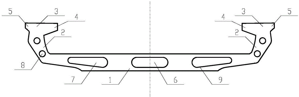
[0029] This rail transit perforated thin-walled prefabricated channel beam includes a supporting base plate 1 and a web 2 extending upward along both sides of the supporting base plate, and a sound-insulating flange plate 3 integral with it is provided on the top of the web 2 , and On the support base plate 1 and the web plate 2, all through-length perforations are reserved.

[0030] Both the support base plate and the upper web are perforated thin-walled structures. By adjusting the width of the support base plate, single-track and double-track tracks can be set. Setting the width of the gradient base plate can meet the requirements of the variable section section of the entrance and exit bell mouth; the sound insulation flange plate is T Type concrete structure, with inner flange 4 and outer flange 5, wherein the size of the inner flange is relatively large. Rail transi...


PUM

PropertyMeasurementUnit
lengthaaaaaaaaaa

Abstract

The invention discloses a perforated thin-wall precast channel beam for rail transit and a precast method of the perforated thin-wall precast channel beam for rail transit. A beam body comprises a bottom support plate, webs, soundproof flange plates and elastic rubber seal parts with hole plugs, wherein the soundproof flange plates are arranged at the tops of the webs. The webs and the soundproof flange plates are in symmetrical arrangement; the bottom support plate is internally provided with a rectangular perforation hole and a trapezoidal perforation hole, the rectangular perforation hole and the trapezoidal perforation hole are optimized to be semicircular in the height direction, and the webs are internally provided with round perforation holes; the elastic rubber seal parts with the hole plugs are arranged at joints of the beam, the thickness of the elastic rubber seal parts is half of the width of the joints, and the two seal parts are closely attached to fill the joints of the beam after beam erection is completed. The perforated thin-wall precast channel beam for rail transit and the precast method of the perforated thin-wall precast channel beam for rail transit have the advantages that the beam body can be stressed more reasonably, a span of the beam body can reach 40m maximally, and accordingly the problem that common U-shaped beams are difficult in crossing of road junctions due to small spans is solved; a soundproof and noise reduction blind area of the beam joints is avoided, so that influences on surroundings due to wheel-track noise and beam structure noise can be effectively reduced; the defect of poor ornamental performance of traditional box beams at positions of entrances and exits is successfully overcome.

Description

technical field [0001] The invention discloses a rail transit perforated thin-wall prefabricated groove beam and a prefabrication method. Background technique [0002] In the Chinese patent application with the application number CN200810304445.3 and the name "U-shaped beam for urban rail transit", compared with other commonly used beam types, the U-shaped beam has the advantages of good landscape effect, excellent noise reduction effect, and high comprehensive cost performance Therefore, it has been widely used in rail transit elevated lines in many cities in recent years, but this U-shaped beam also has the disadvantages of unreasonable force, difficult construction, easy cracking, and poor noise reduction effect at the joint of the two beams , sometimes unable to meet the requirements of rail transit, seriously affecting the large-scale application of U-shaped beams. Contents of the invention [0003] The purpose of the present invention is to solve the problem...

Claims


Application Information

Patent Timeline
Patent Type & Authority Applications(China)
IPC IPC(8): E01D2/00B28B23/04
Inventor 王国富路林海
Owner JINAN RAILWAY TRANSPORT GRP CO LTD
Why Eureka
Try Eureka