
Portable wall space deformation monitoring device for reinforced soil retaining wall and monitoring method

A technology for deformation monitoring and retaining walls, applied to measuring devices for wall deformation of retaining walls, portable reinforced earth retaining wall wall deformation monitoring devices, 0001] The invention belongs to the field of civil engineering and electromagnetism, model trolley The side configuration is applicable to the field, which can solve the problems of poor continuous observation ability, inability to rule out the influence of mechanical performance, poor economy, etc., and achieve the effect of broad application prospects, convenient prototype testing, and simple equipment

Inactive Publication Date: 2015-05-20
CHANGAN UNIV
View PDF5 Cites 8 Cited by
  • Summary
  • Abstract
  • Description
  • Claims
  • Application Information

AI Technical Summary

Problems solved by technology

The main disadvantage of the station observation method is that it is subject to the limitation of terrain visibility conditions and the influence of meteorological conditions, the workload is large, the cycle is long, and the continuous observation ability is poor.
The instrument observation method has high observation accuracy, but its economy is poor. Only the units specialized in observation work have this observation equipment, and it is not commonly used by ordinary personnel for deformation observation.
At the same time, it cannot rule out the impact on the structure and mechanical performance of the retaining wall due to the vertical measuring pipe buried in the retaining wall

Method used


Image

  • Portable wall space deformation monitoring device for reinforced soil retaining wall and monitoring method
  • Portable wall space deformation monitoring device for reinforced soil retaining wall and monitoring method
  • Portable wall space deformation monitoring device for reinforced soil retaining wall and monitoring method

Examples


Embodiment Construction

[0029] see attached below picture The technical scheme of the present invention is further described in detail.

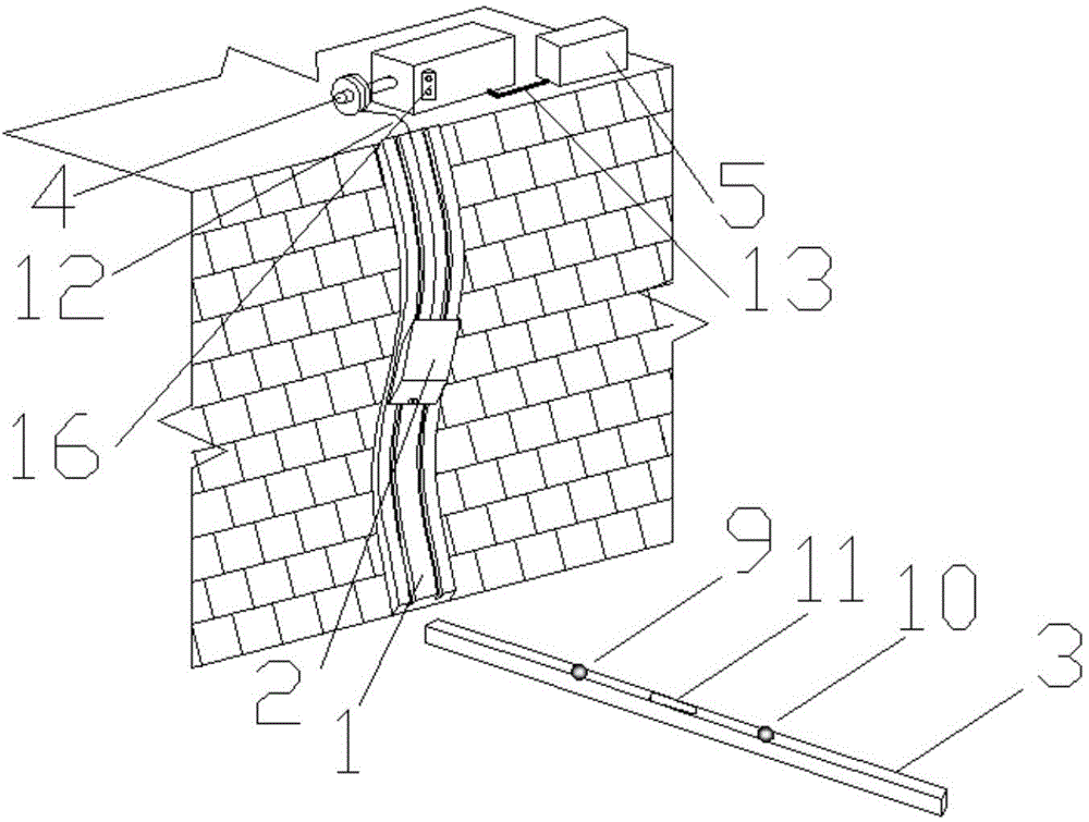
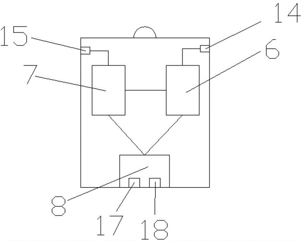
[0030] See attached picture As shown in 1, the portable reinforced soil retaining wall wall deformation monitoring device of the present invention includes a flexible track 1, a test device 2, a signal reflection device 3, a stepping motor 4, an external power supply 5, wires and a traction rope. The signal reflection device is placed at the horizontal position at the bottom of the wall section to be measured, and is perpendicular to the wall. It is a rod with two reflectors installed at both ends; the flexible track is installed on the wall section with measurement, and is close to the wall. ; The test device is a movable device installed on a flexible track; the laser emitting and receiving device provides a signal source for the measurement process and receives the reflected signal; the memory realizes the function of data storage and calculation for the meas...


PUM


Abstract

The invention discloses a portable wall space deformation monitoring device for a reinforced soil retaining wall and a monitoring method. The portable wall space deformation monitoring device for the reinforced soil retaining wall comprises a flexible rail arranged on the fracture surface of a to-be-monitored reinforced soil retaining wall and a testing device arranged on the flexible rail and capable of moving along the flexible rail. The laser ranging technology is applied to the wall space deformation detecting field for a retaining wall, and the application of the laser ranging technology in the wall face deformation detecting practice is achieved, so that the prototype detecting work for the reinforced soil retaining wall is more convenient. Compared with the current monitoring and detecting, the wall space deformation detecting result for the reinforced soil retaining wall is more practical, more objective and more scientific. In addition, multi-purpose (beside from the reinforce soil retaining wall, measuring can be carried out on various flexible walls) in one device is achieved. The device is simple and capable of meeting the requirement of environmental protection, energy conservation and economical efficiency in the present society, so that the application prospect is extremely wide.

Description

technical background [0001] The invention belongs to the fields of civil engineering and electromagnetism, and relates to a measuring device for wall surface deformation of a retaining wall, in particular to a portable reinforced soil retaining wall wall deformation monitoring device and a monitoring method. Background technique [0002] With the continuous development of highway construction in recent years, there are more and more highway ancillary facilities such as high slope engineering projects. In the construction process, it must meet higher requirements in terms of stability and durability. Therefore, how to ensure that the high slope support structure has sufficient safety during its service life, avoid the occurrence of geological disasters, and reduce the personal and property safety of expressway users has become the designer's responsibility for the high slope support structure. Important factors that must be considered when designing. [0003] Deformation...

Claims


Application Information

Patent Timeline
Patent Type & Authority Applications(China)
IPC IPC(8): E02D33/00
CPCE02D29/02E02D33/00
Inventor 贾兴利刘帆刘伟强熊子瑜
Owner CHANGAN UNIV
Learn More