
Industrialization scale pyrolysis treatment system and method for oily sludge

A sludge system and pyrolysis technology, applied in the direction of sludge treatment, pyrolysis treatment of sludge, chemical instruments and methods, etc., can solve the problems of high dust concentration in flue gas, high technical requirements, and shedding of sludge residues, etc., to achieve High emission reduction capacity, improved safety factor, and large processing capacity

Inactive Publication Date: 2017-05-31
PANJIN NINGTAI ENERGY TECH
View PDF5 Cites 35 Cited by
  • Summary
  • Abstract
  • Description
  • Claims
  • Application Information

AI Technical Summary

Problems solved by technology

Rotary kiln incinerators have more rotating parts and slightly more maintenance. They have high mechanical technical requirements, low thermal efficiency, and higher technical conditions than pyrolysis incinerators. The dust concentration in the flue gas is high, accompanied by thermal NOx, especially Crude oil in oily sludge cannot be recycled and cannot meet the large-scale treatment capacity
The chain plate conveyor belt cracking furnace has sludge residues falling off when the chain plate goes down, and the lower cylinder wall is easy to coke, which will cause local overheating of the furnace body, and there are many moving parts inside the chain plate conveyor belt cracking furnace, which requires high processing and manufacturing , the equipment often goes wrong
The whole set of horizontal screw-propelled cracking furnace has a simple structure. The friction between the screw itself and the inner wall can scrape off the coke on the wall, which solves the problem of coking. Due to the short residence time of oily sludge in the furnace, it directly affects the scale and total amount of treated sludge and the problem that the harmless treatment index cannot be achieved.

Method used


Image

  • Industrialization scale pyrolysis treatment system and method for oily sludge
  • Industrialization scale pyrolysis treatment system and method for oily sludge
  • Industrialization scale pyrolysis treatment system and method for oily sludge

Examples


Embodiment Construction

[0036] The present invention will be further described below in conjunction with the accompanying drawings, and of course the following embodiments should not be construed as limiting the present invention.

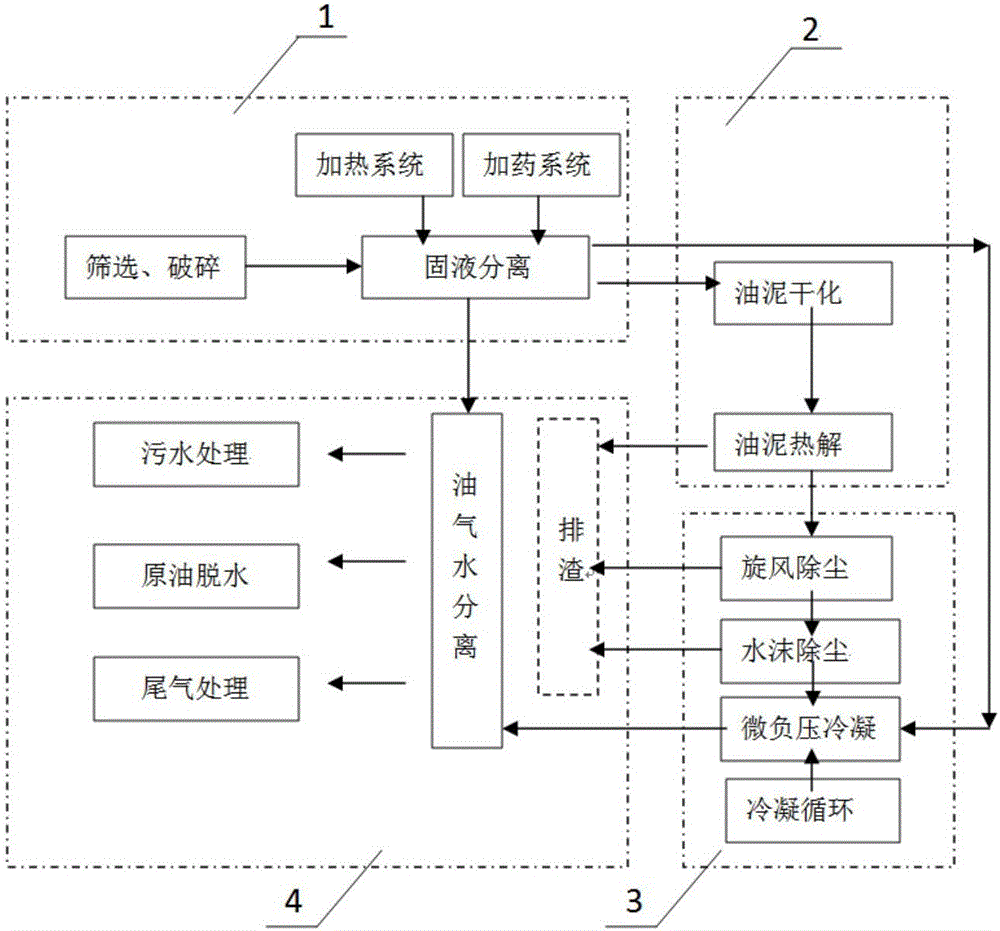
[0037] Such as figure 1 As shown, the present invention is a continuous pyrolysis treatment system and process for oily sludge, including 1-feed pre-sorting unit, 2-drying pyrolysis unit, 3-dust removal and condensation unit and 4-effluent treatment unit;

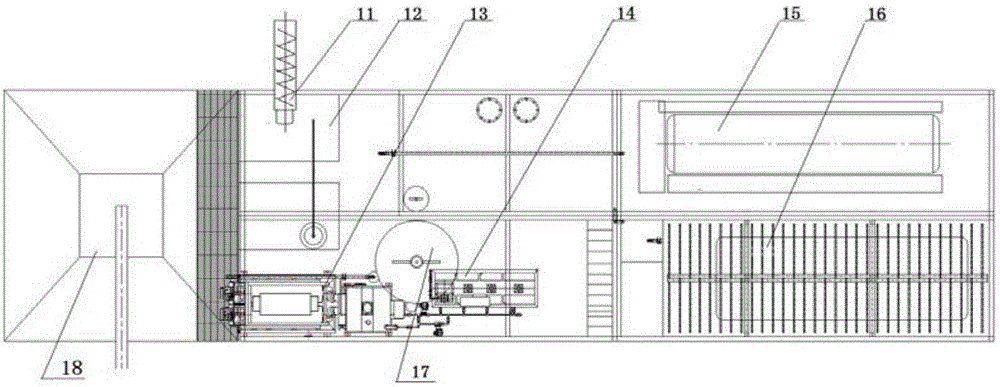
[0038] Such as figure 2As shown, the feed pre-sorting unit 1 includes a feeding screw conveyor 11 , a vibrator 12 , a centrifuge 13 , a mud pump 14 , a heating boiler 15 , an oil-water storage tank 16 , a dosing machine 17 and a sludge collection tank 18 . Firstly, the primary selection is carried out, and the oily sludge is sent to the oil sludge mixing tank by the feeding screw conveyor for dilution and heating, and then pumped into the drum screening device for rough screening, and the solid sand larger than 2mm i...


PUM


Abstract

The invention belongs to the field of waste disposal in petroleum industry, and relates to an industrialization scale pyrolysis treatment system for oily sludge. The industrialization scale pyrolysis treatment system comprises a feeding pre-separation unit for performing secondary screening and solid-liquid separation on the oily sludge, a drying pyrolysis unit for performing drying and pyrolysis reaction on the oily sludge, a dust removal and condensation unit for performing dust removal and condensation on a pyrolysis gas mixture generated by the drying pyrolysis unit, and a discharge treatment unit which receives and treats separated substances of the other units respectively. Solid or solid-liquid mixed waste such as the oily sludge can be finally treated to achieve reduction, stabilization, harmlessness and recycling.

Description

technical field [0001] The invention belongs to the field of waste treatment in the petroleum industry, and relates to an oily sludge treatment system and method, in particular to a large-scale pyrolysis treatment system and method for oily sludge. Background technique [0002] Oily sludge is a kind of solid-liquid mixed waste rich in mineral oil (especially HW08 waste mineral oil) produced in the process of petroleum exploration, mining, storage, transportation and refining. Generally speaking, oily sludge Its appearance is black and viscous, and the oil-in-water, water-in-oil and suspended solid impurities are fully emulsified with each other to form a very stable suspension emulsion system. The longer the storage time, the more difficult it is to handle. Oily sludge is a highly dangerous pollutant, and many countries list it as a highly dangerous pollutant and give priority to controlling hazardous pollutants. [0003] At present, the treatment methods of oily sludge inc...

Claims


Application Information

Patent Timeline
IPC IPC(8): C02F11/00C02F11/10C02F11/14C02F9/14B01D5/00B01D50/00C10G1/00
CPCB01D5/0057B01D53/002C10G1/002C02F9/00C02F11/00C02F11/10C02F11/127C02F11/14C02F1/001C02F1/24C02F3/1268B01D2258/02C10G2300/1003B01D50/40Y02W10/40
Inventor 任杰张弘韬王修文
Owner PANJIN NINGTAI ENERGY TECH
Learn More