Mining anti-explosion coal bunker gas automatic emission control device

A mine explosion-proof and automatic discharge technology, applied in gas discharge, mining equipment, pump control and other directions, can solve the problems of low safety, economic loss, personnel suffocation, etc., to reduce hidden safety hazards, good energy saving effect, and high safety. Effect

Active Publication Date: 2015-05-20
太原双太利安科技有限公司
12 Cites 5 Cited by

AI-Extracted Technical Summary

Problems solved by technology

[0002] Generally, due to the strong adhesion of gas to coal, when coal is transported from underground to underground coal bunkers or ground coal bunkers, a large amount of gas will be brought into the coal bunker. After the gas is separated from the coal, it is easy to accumulate in the coal bunker , cause the gas to exceed the limit, and when the concentration is too high, it will cause suffocation or even death, and may cause a gas explosion, which will bring safety hazards to the safe production of the mine and cause serious economic losses. Therefore, gas disasters have become a threat to mine safety. , An important factor restricting the deve...

Abstract

The invention discloses a mining anti-explosion coal bunker gas automatic emission control device and belongs to the technical field of coal bunker gas emission. A bunker gas automatic emission control system with high safety, good energy-saving effect and capability of real-timely adjusting fan ventilation quantity according to gas concentration in a coal bunker is provided. According to the technical scheme, the mining anti-explosion coal bunker gas automatic emission control device comprises a processor unit, a gas concentration collecting unit, a power supply unit, a fan operation state control unit, a fan operation state monitoring unit, a fan control device, a non-intrinsic electric device control unit and a non-intrinsic electric switch unit, signal output ends of the gas concentration collecting unit and the fan operation state monitoring unit are electrically connected with a signal input end of the processor unit, and a signal output end of the processor unit is electrically connected with signal input ends of the fan operation state control unit and the non-intrinsic electric device control unit. The mining anti-explosion coal bunker gas automatic emission control device is applied to the field of coal mines.

Application Domain

Technology Topic

Image

  • Mining anti-explosion coal bunker gas automatic emission control device

Examples

  • Experimental program(1)

Example Embodiment

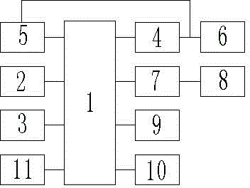
[0013] Such as figure 1 As shown, the mine explosion-proof coal bunker gas automatic emission control device includes: a processor unit 1, a gas concentration acquisition unit 2 and a power supply unit 3. The device also includes: a fan operating state control unit 4, a fan operating state monitoring unit 5 , Fan control equipment 6, non-intrinsically safe electrical equipment control unit 7 and non-intrinsically safe electrical switch unit 8; the signal output terminals of the gas concentration acquisition unit 2 and the fan operating state monitoring unit 5 and the processor unit 1 The signal input terminal of the processor unit 1 is also electrically connected with: an alarm unit 9 and a display unit 10; the signal output terminal of the processor unit 1 is connected to the fan operating state control unit 4 and the non-essential The signal input end of the electrical equipment control unit 9 is electrically connected, and the output end of the fan operating state control unit 4 is electrically connected to the signal input end of the fan operating state monitoring unit 5 and the fan control device 6, respectively. The signal output end of the non-intrinsically safe electrical equipment control unit 9 is connected to the non-intrinsically safe electrical switch unit 8, and the power supply unit 4 is connected to the power supply end of the processor unit 1, which is an AT89S52 single-chip microcomputer .
[0014] In this embodiment, the gas concentration acquisition unit 2 includes two gas concentration sensors, two gas sensors installed in the coal bunker, when any one of the sensors detects that the gas concentration value in the coal bunker is ≥0.1% , The processor unit 1 performs data processing calculations based on the gas concentration value information and the current operation status information of the fan monitored by the fan operation status monitoring unit, and outputs the first level operation status information of the fan to the fan operation status control unit 4, and the fan operation control unit 4 The output signal controls the fan control device 6, so that the counter-rotating local fan of the fan of the ventilation system works in the first-level operation state.
[0015] Specifically, as the gas concentration increases, when the gas concentration value monitored by any gas sensor is 0.1%-0.5%, the output signal of the processor unit 1 maintains the first-level running state against the rotary local fan. When the gas concentration value monitored by the gas sensor is ≥0.5%, the processor unit 1 outputs the secondary operating status information of the fan to the fan operating status control unit 4, so that the counter-rotating local fan of the ventilation system fan works in the secondary operating status, increasing The ventilation volume of the fan of the ventilation system; when the ventilation system works for a period of time, as the gas concentration decreases, when the gas concentration value monitored by any gas sensor is less than 0.5%, the processor unit 1 outputs the first-level operation status information of the fan to The fan operating status control unit 4 restores the counter-rotating local fan to the first-level operating status. When the gas concentration values ​​monitored by the two gas sensors are both <0.1%, the processor unit 1 outputs the fan stop operating status information to the fan operating status Control unit 4, turn off the fan and stop the counter-rotating fan;
[0016] Further, when any sensor detects the gas concentration value ≥ 1%, the processing unit 1 activates an audible and visual alarm by controlling the alarm unit, and when any one makes the gas concentration detected by the sensor ≥ 1.5%, the processor unit 1 The non-intrinsically safe electrical equipment control unit 7 connected to the output port controls the on and off of the non-intrinsically safe electrical switch unit to realize the lockout operation of the related non-intrinsically safe electricity in the coal bunker, and reduce the potential safety hazards caused by excessive gas concentration.
[0017] In this embodiment, the device further includes: a communication unit 11, the processor unit 1 communicates with a host computer through the communication unit 11, and the display unit 10 includes: a display drive unit and four LED digital display tubes , The display drive unit is a MAX7129 chip.
[0018] The invention solves the problems of low safety, poor energy-saving effect, and inability to adjust the ventilation volume of the fan in real time according to the gas concentration in the coal bunker in the traditional coal bunker gas discharge process, and has outstanding substantive characteristics and significant progress; The embodiments of the present invention are described in detail with reference to the accompanying drawings. However, the present invention is not limited to the above-mentioned embodiments. Within the scope of knowledge possessed by those of ordinary skill in the art, various modifications can be made without departing from the purpose of the present invention. Variety.

PUM

no PUM

Description & Claims & Application Information

We can also present the details of the Description, Claims and Application information to help users get a comprehensive understanding of the technical details of the patent, such as background art, summary of invention, brief description of drawings, description of embodiments, and other original content. On the other hand, users can also determine the specific scope of protection of the technology through the list of claims; as well as understand the changes in the life cycle of the technology with the presentation of the patent timeline. Login to view more.

Similar technology patents

System, method and device for execution of payment business

ActiveCN107038560AReduce waiting timeReduce security risksCredit schemesElectronic credentialsOperating systemPayment
Owner:ADVANCED NEW TECH CO LTD

Classification and recommendation of technical efficacy words

  • Reduce security risks
  • Improve security

Automatic driving system

Owner:CHERY AUTOMOBILE CO LTD

Power safety socket device

Owner:东莞科奔电器有限公司

Method and system for powerline networking

InactiveUS20060018328A1Improve securityEasy to changeBroadband local area networksBroadcast transmission systemsComputer network
Owner:COMCAST CABLE COMM LLC
Why Eureka
Try Eureka