Current monitoring system

A technology of current monitoring and current detection, which is applied in the direction of protection against overcurrent and measurement using digital measurement technology. It can solve the problems of easy loopholes, simple monitoring objects, and complicated costs, and achieves convenient installation and simple structure. , Real-time current monitoring and display effect

Inactive Publication Date: 2015-05-20
四川融鑫信息科技有限公司
View PDF0 Cites 3 Cited by
  • Summary
  • Abstract
  • Description
  • Claims
  • Application Information

AI Technical Summary

Problems solved by technology

[0006] The technical problem to be solved by the present invention is: the current monitoring in the prior art usually adopts a mechanical structure, which is relatively complex and costly, and the monitoring object is relatively simple and prone to loopholes

Method used


Image

  • Current monitoring system

Examples


Embodiment Construction

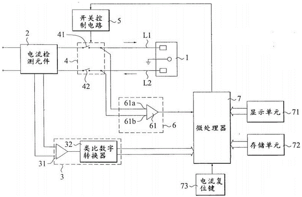
[0019] see figure 1 , shows the current monitoring system of the present invention.

[0020] The current monitoring system is connected to an AC power supply circuit formed by an AC power supply and an electronic device 1, the AC power supply circuit includes a first power line L1 and a second power line L2, and the first power line L1 and the second power supply The line L2 is connected to an AC power source and the electronic device 1 to supply AC power to the electronic device 1 .

[0021] The current monitoring system includes a current detection element 2 , a current signal processing unit 3 , a current switch unit 4 , a switch control circuit 5 , a switch state monitoring unit 6 and a microprocessor 7 .

[0022] The current detection element 2 is coupled to the first power line 1 and the second power line 2 to detect the current on the first power line L1 and the second power line L2, so as to detect whether there is leakage, optional Yes, the current detection element...


PUM


Abstract

A current monitoring system is connected to an alternating-current power supply loop consisting of an alternating-current power supply and an electronic device. The alternating-current power supply loop comprises a first power line and a second power line; the current monitoring system comprises a current detecting element, a current signal processing unit, a current switch unit, a switch control circuit and a microprocessor; the current detecting element is coupled to the first power line and the second power line; the current signal processing unit comprises a signal amplifier and an analog-to-digital converter; and the current switch unit comprises a first selector switch and a second selector switch; the first selector switch is serially connected to the first power line; and the second selector switch is serially connected to the second power line. The current monitoring system is simple in structure; current is monitored in real time by a simple circuit; the current monitoring system is convenient to mount; the circuit does not require to be modified; current can be monitored and displayed in real time; data can also be stored in the current monitoring system; and a data support is provided for a user on follow-up analysis.

Description

technical field [0001] The invention relates to a current monitoring system. Background technique [0002] With the continuous improvement of the degree of automation, more and more electronic devices are automatically monitored, and their applications are becoming more and more extensive. It can not only provide convenient and fast management, but also realize fast processing. [0003] Commonly used electronic device monitoring needs to monitor the current or voltage of the electronic device to know the information of the electric device in time. [0004] This kind of current monitoring in the prior art usually adopts a mechanical structure, which is relatively complex and expensive, and the monitoring object is relatively simple, which is prone to loopholes. [0005] For this reason, in view of the above-mentioned defects, the designer of the present invention researches and designs a current monitoring system to overcome the above-mentioned defects by concentrating on re...

Claims


Application Information

Patent Timeline
Patent Type & Authority Applications(China)
IPC IPC(8): H02H3/08G01R19/25
Inventor 马鸣晓
Owner 四川融鑫信息科技有限公司
Why Eureka
Try Eureka