Method for controlling generator frequency by output torque of prime motors
A technology for outputting torque and prime mover, which is applied to control generators, AC networks with the same frequency from different sources, control systems, etc.
- Summary
- Abstract
- Description
- Claims
- Application Information
AI Technical Summary
Problems solved by technology
Method used
Image

Examples
Embodiment
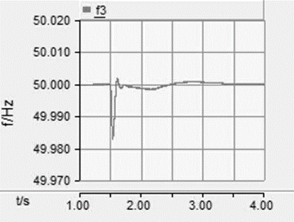
[0035] Embodiment: A method for controlling the generator frequency by using the output torque of the prime mover. Taking IEEE's 3 machines and 9 nodes as a simulation case, it is required that the system quickly converges to 50 Hz when the system suddenly increases 50 MW at t=1.5 s. At the same time, the maximum frequency deviation does not exceed 0.02Hz.
[0036] According to the original data of the IEEE 3-machine 9-node model, data such as line parameters, transformer parameters, load parameters and generator parameters are analyzed and calculated.
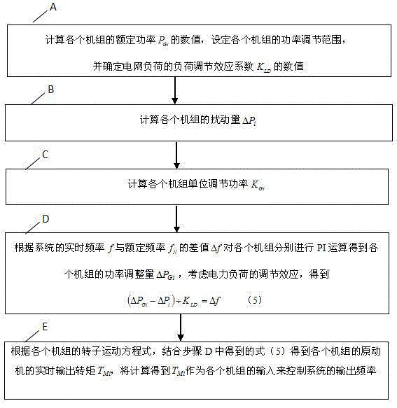
[0037] Such as figure 1 As shown, the control method of the present invention is realized through the following steps:
[0038] A: Calculate the rated power P of each unit Gi value, set the power adjustment range of each unit, and determine the load adjustment effect coefficient K of the grid load LD value.
[0039] In the rated operation of the system, calculate the rated power values P of the three units respectively ...
PUM
 Abstract
Description
Claims
Application Information