
Stator winding structure of brushless coreless disk permanent magnetic motor and motor with the stator winding structure

A permanent magnet motor and stator winding technology, applied in the shape/style/structure of winding conductors, etc., can solve the problems of difficult to accurately design motor power, low utilization rate of magnetic field, and high utilization rate of magnetic field, and achieve high utilization rate of electromagnetic field, The effect of maximizing the sweep area and increasing the strength of the main shaft

Inactive Publication Date: 2015-05-20
吕周安
View PDF1 Cites 4 Cited by
  • Summary
  • Abstract
  • Description
  • Claims
  • Application Information

AI Technical Summary

Problems solved by technology

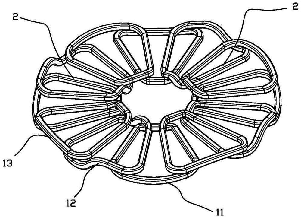
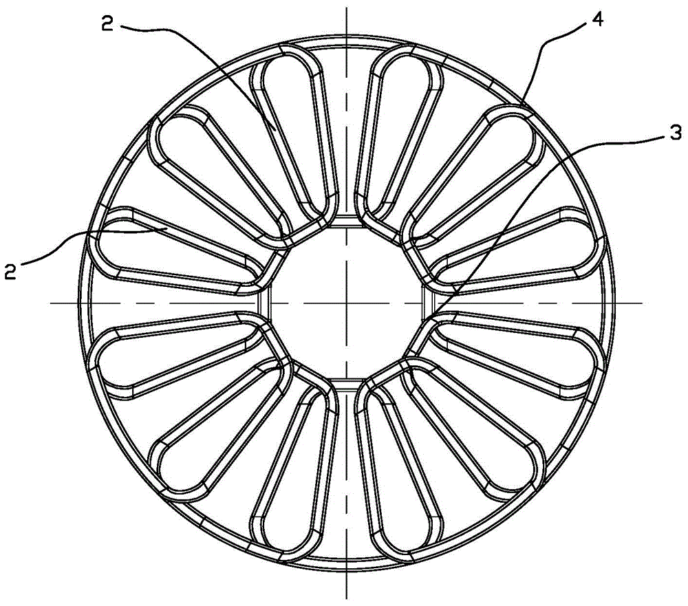
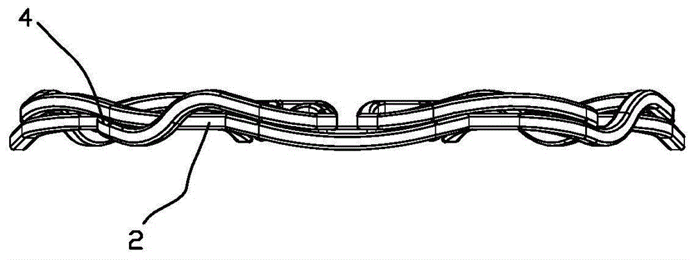
[0003] The invention provides a stator winding structure of a brushless coreless disc permanent magnet motor in which the scanning sides of the magnets of each coil are located in the same plane and have the same height, so that the produced motor has a small volume and a high utilization rate of the magnetic field. The power of the motor can be precisely designed according to the actual needs; it solves the technical problems of the brushless coreless disc permanent magnet motor in the prior art, such as large volume, low utilization rate of the magnetic field, and difficulty in accurately designing the power of the motor.

Method used


Image

  • Stator winding structure of brushless coreless disk permanent magnetic motor and motor with the stator winding structure
  • Stator winding structure of brushless coreless disk permanent magnetic motor and motor with the stator winding structure
  • Stator winding structure of brushless coreless disk permanent magnetic motor and motor with the stator winding structure

Examples


Embodiment 1

[0036] Embodiment 1: as figure 1 , Figure 4 As shown, a stator winding structure of a brushless iron-coreless disc permanent magnet motor, the winding structure includes four sets of unit coil groups 1 with staggered angles and sequentially stacked downwards in the clockwise direction to form a closed ring structure, Each unit coil group 1 includes three coils with staggered angles and sequentially stacked upwards in the clockwise direction, as shown in Figure 5 As shown, the three coils are sequentially the first coil 11, the second coil 12 and the third coil 13 from bottom to top. The ends make the coils constitute the inner and outer invalid sides of the closed ring structure, and the included angles formed by the two magnet scanning sides of each coil are set to be the same. Such as Figure 6 , Figure 7 , Figure 8 As shown, the outer invalid edge on the first coil 11 corresponds to the first outer invalid edge 111, the inner invalid edge on the first coil 11 corre...

Embodiment 2

[0043] Embodiment 2: as Figure 17 As shown, each coil includes four pairs of magnet scanning sides 2 that are straight segments and inner and outer ineffective sides connected to the inner and outer ends of the magnet scanning sides 2 so that the coil forms a closed ring structure, and the outer ineffective sides are arranged on each pair of magnet scanning sides. The outer end of the side is used for the connection of the outer end of the pair of magnet scanning sides, and the inner invalid side is arranged on the inner end of the magnet scanning side, and is used for the connection of the inner end of the adjacent magnet scanning side. In this embodiment, only Three coils with four pairs of magnet scanning sides are required to be stacked. These three coils are the first coil 11, the second coil 12 and the third coil 13 from bottom to top, as Figure 18 , Figure 19 , Figure 20 , Figure 21 As shown, the angle formed by each pair of magnet scanning sides on the first co...


PUM


Abstract

The invention relates to a brushless coreless disk permanent magnetic motor and a stator winding structure therein; the brushless coreless disk permanent magnetic motor comprises two groups of unit coil sets, wherein the unit coil sets are staggered in included angles and laminated downwardly in order along a clockwise direction to form a sealing annular structure; each unit coil set includes three coils that are staggered in the included angles and laminated upwardly in order along the clockwise direction; each coil includes a pair or more than a pair of magnet strafing edges that are straight-line segments, and internal-external invalid edges connected with inner and outer end portions of the magnet strafing edges; the magnet strafing edges of each coil are arranged radially and circumferentially to form a toroidal surface; all magnet strafing edges of the winding are located in the same plane and consistent in height; and the internal-external invalid edges of each coil are laminated mutually to form internal and external superimposition parts of a lower bump. Because all magnet strafing edges of the winding are located in the same plane and consistent in height, the slot fullness of the coils and the utilization rate of the generated electromagnetic field are higher, the efficiency of the motor is improved greatly and the heat productivity of the motor stator is reduced.

Description

technical field [0001] The invention relates to a component of a brushless iron-coreless disc permanent magnet motor, in particular to a winding structure of a stator therein and a motor with the stator winding structure. Background technique [0002] Motor stators now include iron-core motors and iron-less motors. The stator of a motor with an iron core is composed of an iron core and a coil wound on the iron core. Due to the irregular shape of the part of the coil exposed on the top and bottom surfaces of the iron core, there is a little hindrance when installing the rotor in the stator, that is, The rotor cannot be installed, or even if it is installed, the operation of the rotor will be affected. In addition, when the stator is installed in the stator shell, these irregularly shaped partial coils that expose the top and bottom surfaces of the iron core will also affect the installation of the stator itself. Therefore, in After the stator is socketed with wires each time...

Claims


Application Information

Patent Timeline
Patent Type & Authority Applications(China)
IPC IPC(8): H02K3/04H02K3/28
CPCH02K3/04H02K3/28
Inventor 吕周安
Owner 吕周安
Learn More