Connected system of mining vehicle engine and gearbox

A technology for connecting systems and engines, which is applied to vehicle parts, control devices, transportation and packaging, etc., can solve the problems of damage to the engine, transmission system waste of engine output power, transmission shaft shaft weight, etc., to prevent erosion and damage, The effect of reducing the cost of the whole vehicle and improving the transmission efficiency

Active Publication Date: 2015-05-27
东风重工(十堰)有限公司
View PDF8 Cites 3 Cited by
  • Summary
  • Abstract
  • Description
  • Claims
  • Application Information

AI Technical Summary

Problems solved by technology

[0002] The front transmission system of mining vehicles mostly adopts the composition of flexible disc + output flange + non-constant velocity transmission shaft. The non-constant velocity transmission shaft has a heavy transmission shaft tube, which has its own waste; at the same time, because the mining vehicle has been running at a low speed, the transmission accuracy of the non-constant velocity transmission shaft cannot be realized (mainly the non-constant velocity transmission shaft pair The installation requirement is higher than that of the constant velocity transmission shaft, which has a great impact on the vibration of the transmission system), resulting in the waste of the entire transmission system and the failure to maximize the output power of the engine (the transmission efficiency of the non-constant velocity transmission shaft is higher than that of the constant velocity transmission shaft Low)
[0003] The front transmission system...

Method used


Image

  • Connected system of mining vehicle engine and gearbox
  • Connected system of mining vehicle engine and gearbox
  • Connected system of mining vehicle engine and gearbox

Examples


Embodiment Construction

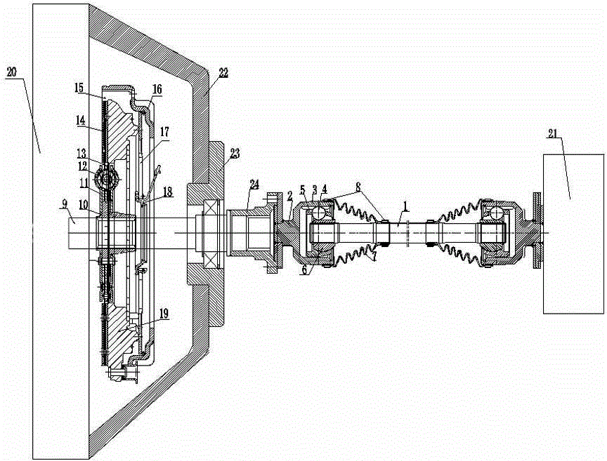
[0025] The present invention as figure 1 , 2 , 3 shown.

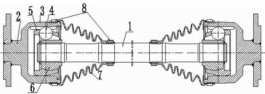
[0026] The connection system between the mining vehicle engine and the gearbox includes the engine 20 and the gearbox 21, the engine 21 is provided with a bearing housing 22, the engine output shaft 9 extends in the bearing housing 22, and the bearing housing 22 is provided with There is a driven plate assembly, and the clutch pressure plate assembly is correspondingly arranged outside the driven plate assembly; the engine output shaft 9 runs through the driven plate assembly and the clutch pressure plate assembly and extends out of the housing 22 of the bearing housing. On the bearing seat 23; the outer bearing seat 23 is connected with a first transmission shaft 24, and between the first transmission shaft 24 and the gearbox 21 is connected with a constant speed transmission system.

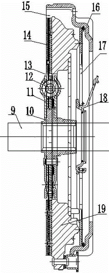
[0027] The center of the driven disc assembly is a spline sleeve 10, the spline sleeve 10 is connected with a driven disc hub 11, the...


PUM


Abstract

The invention discloses a connected system of a mining vehicle engine and a gearbox. The connected system comprises an engine and a gearbox, wherein a bearing seat shell is arranged behind the engine, the engine output shaft is extended in the bearing seat shell, a driven disc assembly is arranged in the bearing seat shell, and the outside of the driven disc assembly is correspondingly provided with a clutch pressure plate assembly; the engine output shaft passes through the driven disc assembly and the clutch pressure plate assembly, gets out and extends onto the bearing seat at the outside of the bearing seat shell; the outside of the bearing seat is connected with a drive shaft 1, and a constant speed drive system is connected between the drive shaft 1 and the gearbox. The driven disc assembly, the clutch pressure plate assembly and the constant speed drive system are organically combined into one to form a connected system of the mining vehicle engine and the gearbox according to the invention; the connected system of the mining vehicle engine and the gearbox has the advantages that the structure is simple, the manufacture and maintenance are convenient, the reliability is high, and the max compaction power can reach 55,000N.m, the greater torque can be transferred, the influence of the vibration of the drive system on vehicle parts is reduced, the service life of the drive system is prolonged, and the vehicle cost is lowered to the maximum extent.

Description

technical field [0001] The invention relates to a mining vehicle, in particular to a connection system between a mining vehicle engine and a gearbox. Background technique [0002] The front transmission system of mining vehicles mostly adopts the composition of flexible disc + output flange + non-constant velocity transmission shaft. The non-constant velocity transmission shaft has a heavy transmission shaft tube, which has its own waste; at the same time, because the mining vehicle has been running at a low speed, the transmission accuracy of the non-constant velocity transmission shaft cannot be realized (mainly the non-constant velocity transmission shaft pair The installation requirement is higher than that of the constant velocity transmission shaft, which has a great impact on the vibration of the transmission system), resulting in the waste of the entire transmission system and the failure to maximize the output power of the engine (the transmission efficiency of the ...

Claims


Application Information

Patent Timeline
IPC IPC(8): B60K17/02B60K17/06B60K17/22
Inventor 黄星光陈雄王泓姚磊肖海峰
Owner 东风重工(十堰)有限公司
Why Eureka
Try Eureka