Multifunctional friction wear testing machine

A friction and wear test, multi-functional technology, applied in the direction of testing wear resistance, using mechanical devices, measuring devices, etc., can solve the problems of complex structure and high cost, and achieve the effect of low cost, complete functions and simple structure

Inactive Publication Date: 2015-05-27
NANJING FORESTRY UNIV
View PDF10 Cites 25 Cited by
  • Summary
  • Abstract
  • Description
  • Claims
  • Application Information

AI Technical Summary

Problems solved by technology

However, each set of lower friction pair motion modules of the testing machine has a motion device including motors and other components to achieve the corresponding motion form, which has a complex structure and high cost

Method used


Image

  • Multifunctional friction wear testing machine
  • Multifunctional friction wear testing machine
  • Multifunctional friction wear testing machine

Examples


Embodiment 1

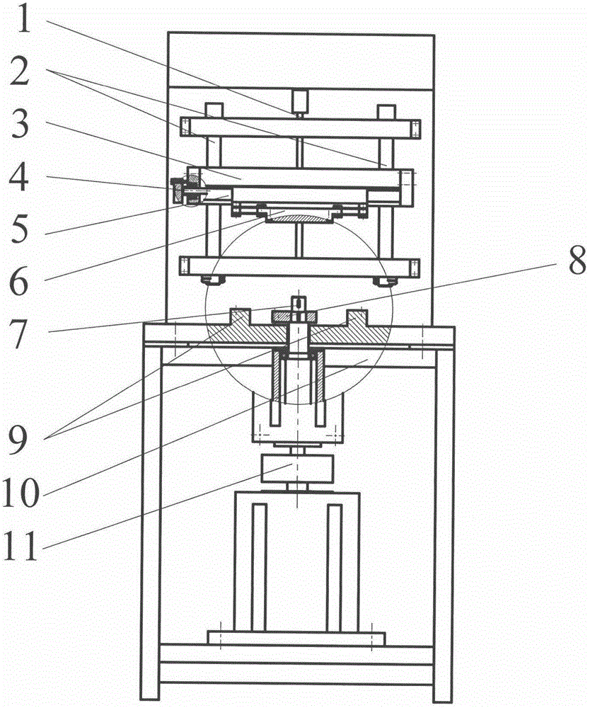
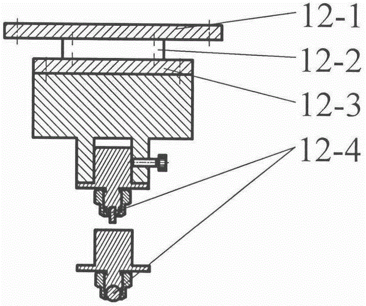
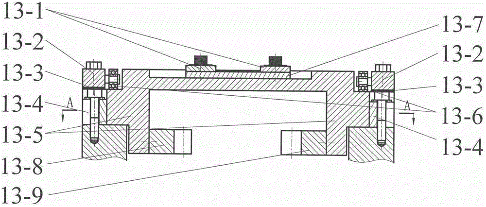
[0026] Embodiment one: if figure 1 As shown, a multifunctional friction and wear testing machine body includes a vertical screw 1, a vertical guide column 2, a cantilever bracket 3, a horizontal screw 4, a horizontal guide column 5, an upper friction pair coupling seat 6, a rotating main shaft 7, an incomplete Gear 8, rectangular guide rail 9, frame 10, synchronous belt drive 11. If the test machine is used as Image 6 The tribological test of the pin (ball) upper friction pair 12-4 and the reciprocating lower friction pair 13-7 shown, before the test, the pin (ball) upper friction pair assembly 12 needs to be screwed to the upper friction pair coupling seat 6 Put the upper friction pair 12-4 on the pin (ball) in the upper friction pair assembly 12 of the pin (ball) and fasten it with a nut; place the reciprocating lower friction pair assembly 13 on the rectangular guide rail 9 of the frame 10 , and make the left rack 13-8 in the reciprocating lower friction pair assembly 13...

Embodiment 2

[0027] Embodiment two: if use testing machine to carry out such as Figure 9 For the tribological test of the friction pair 14-10 on the end face and the friction pair 15-1 on the lower end face shown, it is necessary to install the upper friction pair assembly 12 on the pin (ball) mounted on the upper friction pair coupling seat 6 and the rectangular guide rail 9 The reciprocating lower friction pair assembly 13 is removed, and then the friction pair assembly 14 on the end face is fixed on the upper friction pair coupling seat 6 with screws, the lower friction pair assembly 15 on the end face is set on the rotating main shaft 7, and then the friction pair assembly 14 on the end face 14-10 and the friction pair 15-1 under the end face are respectively placed in the friction pair assembly 14 on the end face and the friction pair assembly 15 under the end face, and fastened with set screws. Among them, the friction pair assembly 14 on the end face is composed of a friction pair ...

Embodiment 3

[0028] Embodiment three: if use testing machine to carry out such as Figure 11 For the tribological test of the upper friction pair 12-4 of the pin (ball) and the lower friction pair 16-1 of the rotating disk, the friction pair assembly 14 installed on the end surface of the upper friction pair coupling seat 6 and the friction pair assembly 14 installed on the rotating main shaft 7 are required. Disassemble the lower friction pair assembly 15 on the upper end face, then put the lower friction pair assembly 16 on the rotating main shaft 7, and place the lower friction pair 16-1 in the lower friction pair assembly 16 of the rotating disk. Fasten the set screw; fix the friction pair assembly 12 on the pin (ball) on the upper friction pair connection seat 6 with screws, and place the upper friction pair assembly 12-4 on the pin (ball) on the friction pair assembly 12 on the pin (ball) In the process, fasten with a nut, turn the horizontal lead screw 4 to drive the friction pair a...


PUM


Abstract

The invention discloses a multifunctional friction wear testing machine, which comprises a vertical screw rod, a vertical guide post, a cantilever support, a horizontal screw rod, a horizontal guide post, an upper friction pair connecting seat, a rotary main shaft, an intermittent gear, a rectangular guide rail, a rack, a synchronous belt drive, a pin (ball) upper friction pair assembly, a reciprocating lower fiction pair assembly, an end-face upper friction pair assembly, an end-face lower friction pair assembly and a rotary disk lower fiction pair assembly. The multifunctional friction wear testing machine is characterized in that the different paired friction pair assemblies are exchanged on the upper friction pair connecting seat and the rotary main shaft, so that determination of tribological parameters between the pin (ball) upper friction pair assembly and the reciprocating lower fiction pair assembly, between the end-face upper friction pair assembly and the end-face lower friction pair assembly, and between the pin (ball) friction pair assembly and the rotary disk lower fiction pair assembly is realized. The testing machine can perform tribological experiments of three friction pairs with different forms. Compared with an existing friction wear testing machine, the multifunctional friction wear testing machine is complete in function, simple in structure and low in cost.

Description

technical field [0001] The invention belongs to the field of friction and wear testing machine design, and particularly relates to a friction pair on a pin (ball) and a reciprocating lower friction pair, a friction pair on an end face and a lower friction pair on an end face, and an upper friction pair on a pin (ball) and a lower friction pair on a rotating disk. Multifunctional friction and wear testing machine for three different types of friction pairs. Background technique [0002] There is friction between the relative moving parts of mechanical equipment, and the abnormal friction and wear caused by improper lubrication will not only affect people's production activities, but also cause a huge waste of social wealth. In order to study the phenomenon of friction and wear and its essence, and to correctly evaluate the influence of materials and environment on friction and wear, the friction and wear testing machine is an indispensable test equipment. [0003] According ...

Claims


Application Information

Patent Timeline
Patent Type & Authority Applications(China)
IPC IPC(8): G01N3/56G01N19/02
Inventor 马晨波于波王伟涂桥安孙见君
Owner NANJING FORESTRY UNIV
Why Eureka
Try Eureka