Nuclear reactor direct safety injection system

A nuclear reactor, direct technology, applied in the direction of reactors, nuclear engineering, nuclear power generation, etc., can solve the problems of large thermal shock, increase of diversion devices, safety injection effect and poor anti-bypass flow, etc., to achieve good flow conductivity, control and ease the effect of the upgrade

Active Publication Date: 2015-05-27
CHINA NUCLEAR POWER TECH RES INST CO LTD +2
View PDF8 Cites 12 Cited by
  • Summary
  • Abstract
  • Description
  • Claims
  • Application Information

AI Technical Summary

Problems solved by technology

like figure 1 As shown, the U.S. Patent Publication No. US5377242 discloses a safety injection device, which is to arrange a rectangular chamber 30 ′ between the pressure vessel 10 ′ and the hanging basket 20 ′, and directly install the injection nozzle 40 ′. The outlet 41' is opposite to the inlet of the rectangular chamber 30', and there is no transitional flow guiding part between the two, so that the cooling liquid flows directly along the rectangular chamber 30' to the bottom of the pressure vessel 10', speeding up The flow of coolant to the core; since there is no guide device in the middle of the safety injection device, the pipe and pressure vessel 10` are subjected to a large thermal shock force during the safety injection process, and the coolant flows downward along the rectangular chamber 30` Uneven flow, resulting in vibration, poor safety injection effect and anti-bypass performance
[0012] like figure 2 , Figure 3a and Figure 3b As shown, the U.S. Patent Publication No. US7889830B2 discloses a safety injection device, the safety injection device has a flow guiding device 50 ′, and the flow guiding device 50 ′ is a shallow groove structure with a groove 51 ′. The position of the injection nozzle 40' is processed with a radian structure 52' that guides the cooling liquid to change its direction. The flow direction of the liquid changes, that is, it flows downward; the diversion device is installed on the hanging basket 20`, limited by the thickness of the hanging basket 20`, its arc radius is very small, so that the cooling liquid turns too sharply and cannot be well Organize the cooling liquid to flow downward in an orderly manner, so that the cooling liquid will vibrate violently when flowing downward, and the safety injection effect and anti-bypass performance are poor; and in particular, a flow guide device is added, and the flow guide device is welded on the hanging basket 20' It brings certain technical difficulties to the subsequent installation process of the hanging basket 20` and the docking work with the direct injection nozzle 10`, and also increases the complexity of the structure
[0013] like Figure 4 As shown, the U.S. Patent Publication No. US7983377B2 discloses a safety injection device. In the safety injection device disclosed in this patent, a diversion channel 21` is installed on the hanging basket 20`, and the safety injection nozzle 40` directly faces the diversion groove. On the one hand, when the safety injection process occurs, the initial flow rate and impact force of the coolant are relatively large, and the turning radius of the coolant in the diversion channel 21' is small, so that the coolant cannot completely follow the The diversion channel 21` flows downward in an orderly manner, causing violent vibrations when the coolant flows downward, and the safety injection effect and anti-bypass performance are poor

Method used


Image

  • Nuclear reactor direct safety injection system
  • Nuclear reactor direct safety injection system
  • Nuclear reactor direct safety injection system

Examples


Embodiment approach

[0046] combine Figure 7-8a As shown, preferably, the distribution holes 62 are evenly distributed with the center of the flow distribution member 60 as the center O.

[0047] combine Figure 7-8a As shown, preferably, the distribution holes 62 on the same diameter with the center O of the flow distribution member 60 as the center are the same.

[0048] combine Figure 7-8aAs shown, preferably, the distribution hole 62 of the flow distribution member 60 gradually becomes smaller from bottom to top; that is, the size of the distribution hole 62 on each level is the same, and the distribution holes 62 of different levels are vertically smaller. Multiple rows of holes are formed on the top, and the distribution holes 62 in the upper row are smaller in diameter than the distribution holes 62 in the lower row.

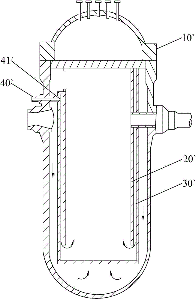
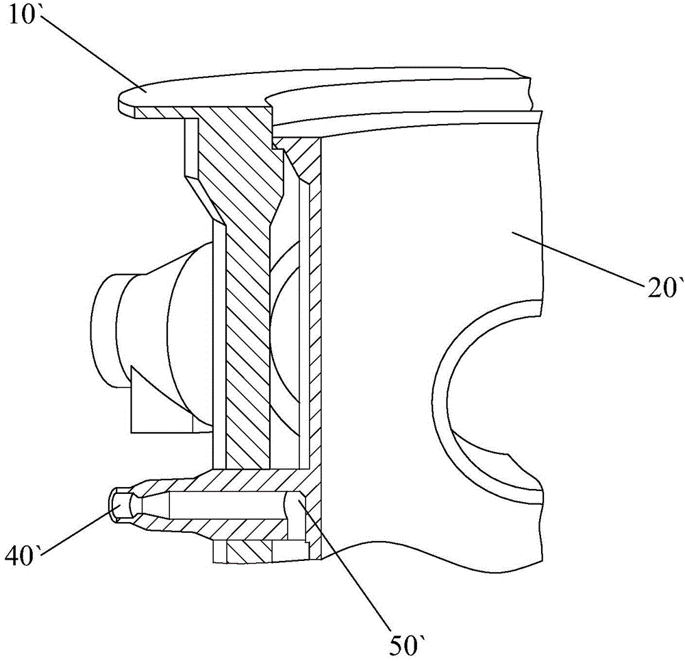
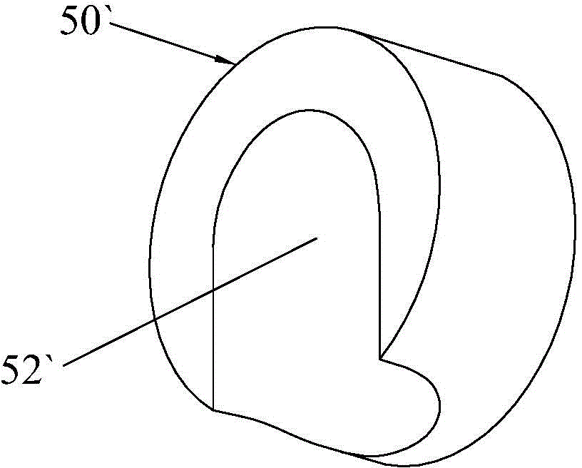
[0049] In order to further improve the efficiency and uniformity of the cooling liquid delivered by the direct injection pipe, combined with Figure 5-Figure 8a As show...


PUM


Abstract

The invention discloses a nuclear reactor direct safety injection system which is used for directly offering cooling liquid to a pressure container in a nuclear reactor, wherein a hanging basket is arranged inside the pressure container; a nuclear reactor core is arranged inside the hanging basket; an annular cavity is formed between the pressure container and the hanging basket; the safety injection system comprises a safety injection cold source and a direct safety injection tube; the direct safety injection tube has an inlet and an outlet; the inlet is communicated with the safety injection cold source; the direct safety injection tube penetrates into the pressure container and extends into the annular cavity, and the outlet is formed below the nuclear reactor core. Since the direct safety injection tube penetrates into the pressure container and extends into the annular cavity, and the outlet is formed just below the nuclear reactor core, when loss of coolant accident occurs, the cooling liquid can be directly conveyed into the nuclear reactor core by virtue of the direct safety injection tube, so as to cool and boronize the nuclear reactor core timely and effectively, greatly improve the capacity of controlling and relieving accidents and effectively prevent the loss of coolant accident from developing to a hyper design basis accident.

Description

technical field [0001] The invention relates to a nuclear reactor safety device, in particular to a nuclear reactor direct safety injection system for providing cooling liquid for a nuclear reactor pressure vessel. Background technique [0002] With the maturity of nuclear energy utilization technology, the safety of nuclear power plants has been continuously improved, and the construction of nuclear power plants has gradually become an important energy guarantee for national development. [0003] In the current nuclear power plant, the structure of the nuclear reactor is: a reactor cavity is formed in the containment vessel, a pressure vessel is arranged in the reactor cavity, a hanging basket is arranged in the pressure vessel, and a nuclear reactor core is arranged in the hanging basket. The pressure vessel is connected with cold and heat pipes, and the cooling liquid is injected through the cold pipe section to cool the pressure vessel, and then discharged through the ho...

Claims


Application Information

Patent Timeline
Patent Type & Authority Applications(China)
IPC IPC(8): G21C15/18
CPCG21C15/18Y02E30/30
Inventor 杨江王婷卢向晖崔军沙正峰庄程军林维青林建树林支康方思远陶俊毛玉龙蒋晓华
Owner CHINA NUCLEAR POWER TECH RES INST CO LTD
Why Eureka
Try Eureka