Ethernet test instrument based on 100G communication and test method thereof

A technology of testing instruments and testing methods, applied in data exchange networks, digital transmission systems, electrical components, etc., can solve problems such as inability to test Ethernet links and equipment, and achieve the effect of enhancing accuracy, stability, and simple structure

Inactive Publication Date: 2015-05-27
OPWILL TECH BEIJING
View PDF4 Cites 6 Cited by
  • Summary
  • Abstract
  • Description
  • Claims
  • Application Information

AI Technical Summary

Problems solved by technology

[0005] The existing 100G Ethernet is widely used in all network layer transmissions, including backbone transmission systems, border routers, data center switching systems, etc. It mainly completes data transmission communication and monitoring functions, and its significant disadvantage is that it cannot Links and devices are fully tested

Method used


Image

  • Ethernet test instrument based on 100G communication and test method thereof
  • Ethernet test instrument based on 100G communication and test method thereof
  • Ethernet test instrument based on 100G communication and test method thereof

Examples


Embodiment 1

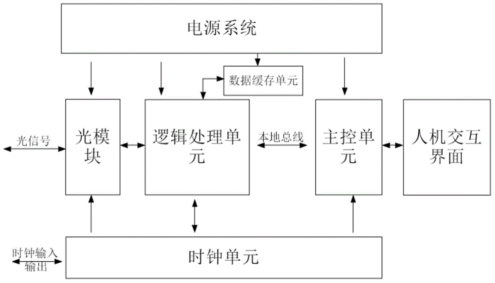
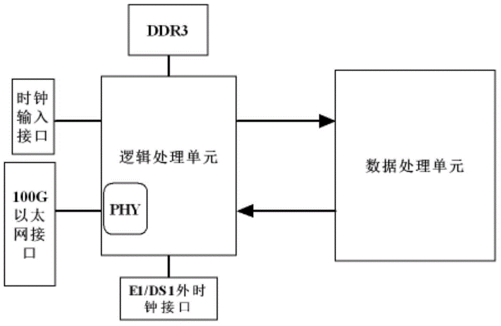
[0019] Please refer to figure 1 , the Ethernet test instrument based on 100G communication of the present invention is realized by an FPGA programmable logic device, including: a 100G optical module, which is used to receive a serial 100G optical signal and convert it into a parallel 10×10G, or 4×25G Electric signal, then carry out data exchange between FPGA; High-speed cache unit, is used for caching it after FPGA reads described parallel data; Main control unit, is used for sending test order to FPGA; Logic processing unit, uses After receiving the test instruction, the Ethernet frame structure test is performed on the parallel data cached by the cache unit.

[0020] Preferably, the transmission operation of the parallel 10×10G electrical signal is: sending and receiving 10 pairs of differential signal lines, each pair of signal lines transmitting 10Gbit / s data.

[0021] Preferably, the parallel 4×25G electrical signal transmission operation is: sending and receiving 4 pair...

Embodiment 2

[0064] This embodiment provides a test method for an Ethernet test instrument based on 100G communication, which is implemented by an FPGA programmable logic device, including: a 100G optical module receives a serial 100G optical signal and converts it into a parallel 10×10G, or 4 ×25G electrical signal, and then perform data exchange with the FPGA; the cache unit caches the parallel data after the FPGA reads it; the main control unit sends a test command to the FPGA; the logic processing unit receives the test command, An Ethernet frame structure test is performed on the parallel data cached by the cache unit.

[0065] Preferably, the Ethernet frame structure is a 100GE Ethernet frame structure meeting 802.3ba.

[0066] Preferably, said performing the Ethernet frame structure test includes testing throughput, the test method is: in the test, a certain number of frames are sent at a certain rate, and the frames transmitted by the device under test are calculated, if the number...


PUM


Abstract

The invention discloses an Ethernet test instrument based on 100G communication and a test method thereof. The Ethernet test instrument is realized by an FPGA (Field Programmable Gate Array). The Ethernet test instrument comprises a 100G optical module, a caching unit, a main control unit and a logical processing unit, wherein the 100G optical module is used for receiving serial 100G optical signals and converting the 100G optical signals into parallel 10*10G electrical signals and then carrying out data exchange with the FPGA; the caching unit is used for caching parallel data after the parallel data are read by the FPGA; the main control unit is used for sending out a test instruction to the FPGA; the logical processing unit is used for receiving the test instruction and carrying out Ethernet frame structure testing on the parallel data cached by the caching unit. The Ethernet test instrument has the advantages that on one hand, the generation, collection, caching and analysis for the data can be completed, and then the simulation analysis for 100G high-speed Ethernet is realized; on the other hand, the Ethernet frame structure testing including the testing of handling capacity, time delay, frame loss and back-to-back can be carried out, so that statistical analysis for Ethernet packages is realized.

Description

technical field [0001] The invention belongs to the field of communication testing and relates to an Ethernet testing instrument and testing method based on 100G communication. Background technique [0002] As early as 2006, IEEE began to study the next-generation high-speed Ethernet 100G standard, and in 2010, the 100G Ethernet standard was approved. Since then, 100G Ethernet has started its commercial journey, and 100G Ethernet Network product platforms and line cards have also been launched by manufacturers. However, up to now, 100G Ethernet services have not been widely popularized. In 2014, the rapid development of the mobile Internet brought explosive growth of data services and broadband services, which consumed a large amount of bandwidth and faced unprecedented severe challenges in carrying capacity. The development of 100G Ethernet technology has once again become the focus of attention. [0003] In recent years, my country's cloud computing market has developed ...

Claims


Application Information

Patent Timeline
Patent Type & Authority Applications(China)
IPC IPC(8): H04L12/26
Inventor 朱天全鲍胜青赵改革
Owner OPWILL TECH BEIJING
Why Eureka
Try Eureka