Eureka AIR delivers breakthrough ideas for toughest innovation challenges, trusted by R&D personnel around the world.

Cold trap

A cold trap and cold plate technology, which is applied in the directions of condensation traps/cold partitions, refrigeration and liquefaction, lighting and heating equipment, etc., can solve the problems of reduced exhaust flow path conductivity and reduced exhaust flow path cross-sectional area. , to achieve the effect of increasing the exhaust velocity and suppressing the decrease of the conductivity

Active Publication Date: 2015-06-03
SUMITOMO HEAVY IND LTD
View PDF8 Cites 4 Cited by
  • Summary
  • Abstract
  • Description
  • Claims
  • Application Information

AI Technical Summary

Problems solved by technology

However, at this time, since a part of the exhaust flow path is occupied by the cold plate, the cross-sectional area of ​​the exhaust flow path is reduced, and the conductance of the exhaust flow path becomes smaller.

Method used


Image

  • Cold trap
  • Cold trap
  • Cold trap

Examples


Embodiment Construction

[0016] Hereinafter, embodiments of the present invention will be described in detail with reference to the drawings. In addition, in the description, the same reference numerals are assigned to the same elements, and overlapping descriptions are appropriately omitted. In addition, the structures described below are examples and do not limit the scope of the present invention in any way.

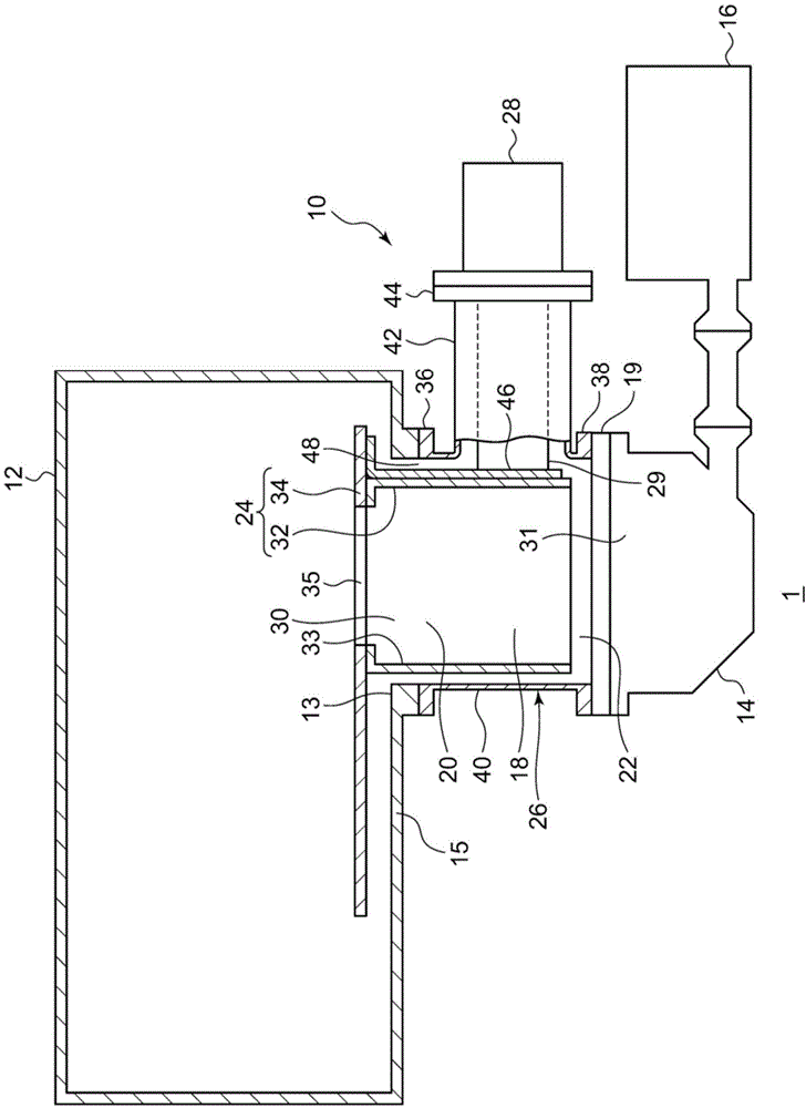
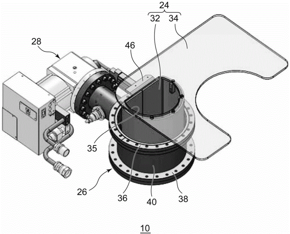
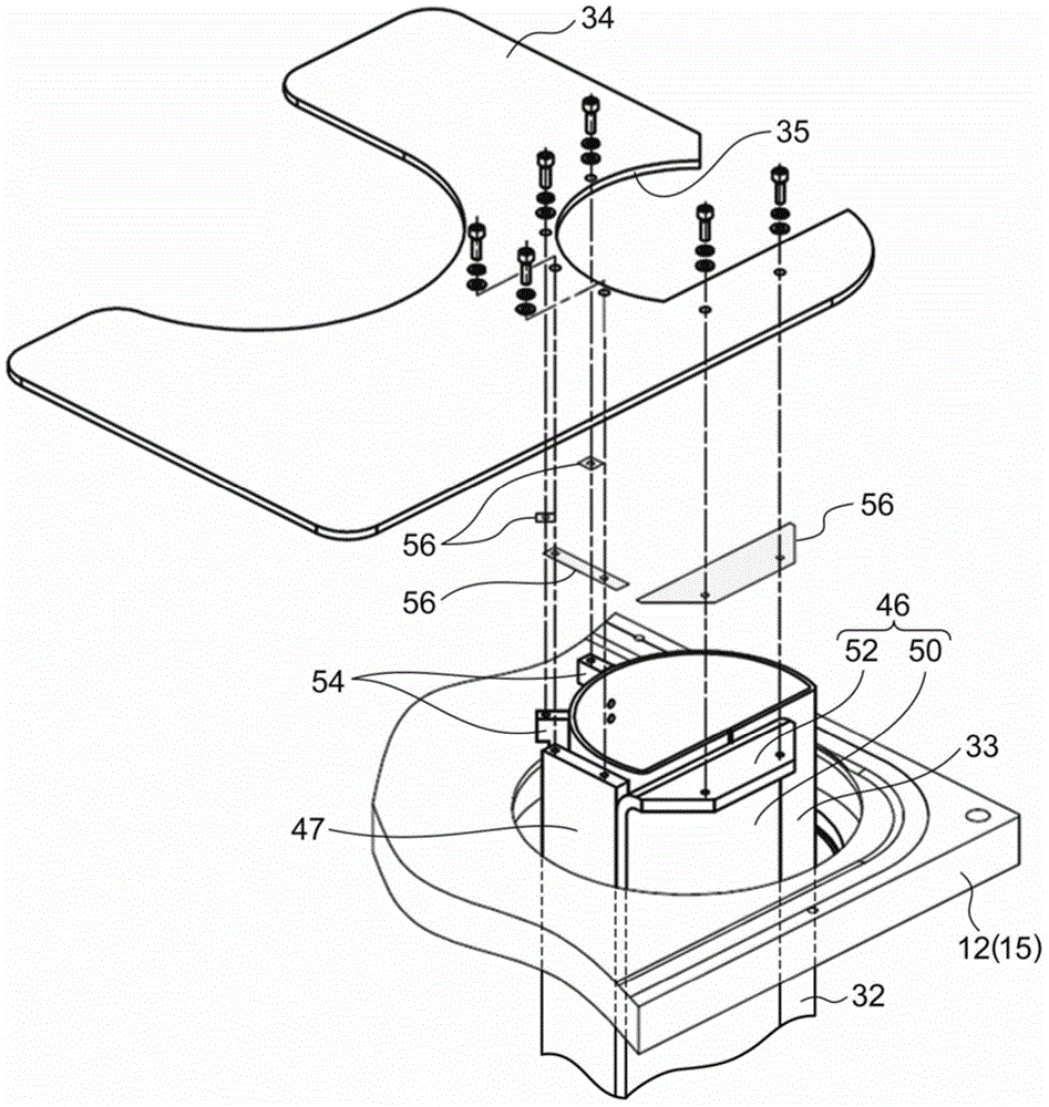
[0017] figure 1 It is a cross-sectional view schematically showing the vacuum evacuation system 1 according to one embodiment of the present invention. figure 2 It is a perspective view schematically showing the cold trap 10 according to one embodiment of the present invention. image 3 It is an assembly diagram schematically showing a part of the cold trap 10 according to one embodiment of the present invention.

[0018] Such as figure 1 As shown, the vacuum evacuation system 1 includes a cold trap 10 and a main vacuum pump (such as a turbomolecular pump 14 ) for evacuating a volume to ...


PUM


Abstract

A cold trap is provided between a vacuum chamber and a vacuum pump. The cold trap includes a cold panel and a cold panel chamber that surrounds the cold panel in an exhaust passage. The cold panel includes an expansion panel outside the cold panel chamber. The expansion panel is located in the vacuum chamber.

Description

[0001] This application claims priority based on Japanese Patent Application No. 2013-249351 filed on December 2, 2013. The entire contents of this Japanese application are incorporated herein by reference. technical field [0002] The invention relates to a cold trap. Background technique [0003] Among cold traps, there is a so-called linear type that is arranged between a vacuum vessel and a vacuum pump. A cold plate is arranged in the exhaust flow path connecting the exhaust port of the vacuum container and the suction port of the vacuum pump. The vacuum pump is, for example, a turbomolecular pump. When a linear cold trap is used with a turbomolecular pump, the cold trap is mainly used to remove water vapor. [0004] Patent Document 1: Japanese Patent Laid-Open No. 2009-262083 [0005] Enlarging the area of ​​the cold plate is a method to increase the exhaust speed of the cold trap. However, at this time, since a part of the exhaust flow path is occupied by the cold...

Claims


Application Information

Patent Timeline
Patent Type & Authority Applications(China)
IPC IPC(8): B01D8/00
CPCB01D8/00
Inventor 谷津贵裕
Owner SUMITOMO HEAVY IND LTD
Why Eureka
Eureka Blog
Learn More