Laterally-split bionic two-tailed paddle unit

A technology of horizontal opening and tail rotor, which is applied to the oars of ships. It can solve the problems of propeller turbulence, high speed and high complexity, and achieve the effect of low hydrodynamic noise, low mechanical noise and high propulsion efficiency

Inactive Publication Date: 2015-06-03
HARBIN ENG UNIV
View PDF7 Cites 4 Cited by
  • Summary
  • Abstract
  • Description
  • Claims
  • Application Information

AI Technical Summary

Problems solved by technology

There are following disadvantages in this way of propulsion: one is that the propulsion efficiency is not high
The second is that the displacement of the propeller is small, and a larger rotational speed is required to obtain greater propulsion. When the propeller rotates at a high speed, turbulence will be generated, resulting in a waste of energy
[0004] The research and experiment of fish-like propulsion mainly focus on the mathematical modeling and simulation of the swing of the flexible tail fin of fish. Some research and experimental results have been obtained, but the implementation is extremely complicated and difficult to be practical. The main problem lies in the underwater environment. The contradiction between the complexity and the limitations of mathematical models, especially the research goals and realization methods in this area are all based on fish, and the flexibility of current materials and mechanical devices cannot reach the level of biological fish

Method used


Image

  • Laterally-split bionic two-tailed paddle unit
  • Laterally-split bionic two-tailed paddle unit
  • Laterally-split bionic two-tailed paddle unit

Examples


Embodiment Construction

[0021] The present invention is described in more detail below in conjunction with accompanying drawing example:

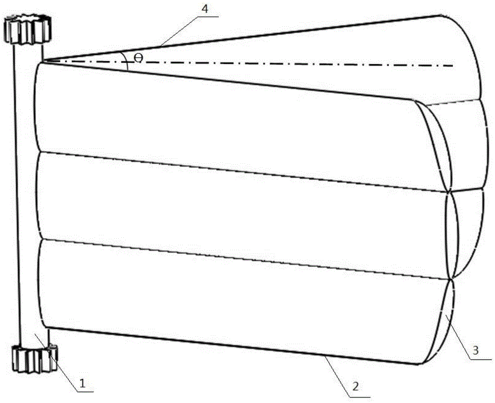
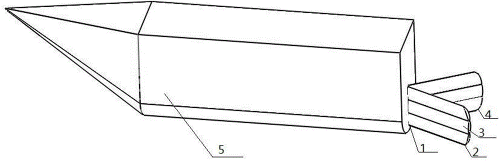
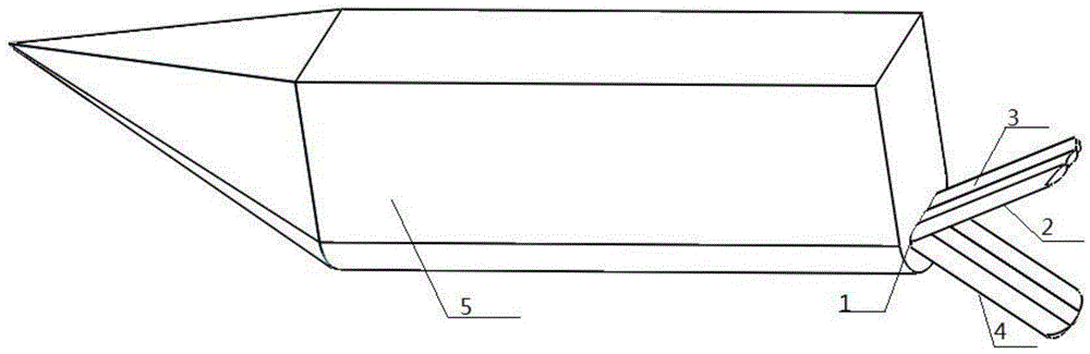
[0022] combine Figure 1-8 , the present invention is composed of two sub-paddles, respectively the first sub-paddle 2 and the second sub-paddle 4, the relative positions of the two are fixed, and the angle θ is kept at 60 to 90 degrees, so as to figure 1 The dotted line is the axis of symmetry distributed on both sides of the main shaft 1, and each sub-paddle is equipped with a number of paddles 3 in parallel, which are connected to the main shaft 1 through the paddle shaft 6. The top of the paddle shaft 6 is a gear structure, which is connected to the main shaft 1 The tooth structure is connected to realize the free rotation of the paddle from 0 degrees to 90 degrees. Both ends of the main shaft 1 are of gear structure, connected with the hull 5, and swing reciprocatingly under the drive of the hydraulic transmission system in the hull 5. The main shaft and ea...


PUM


Abstract

The invention aims to provide a laterally-split bionic two-tailed paddle unit comprising a spindle, a first sub-paddle component and a second sub-paddle component. The spindle is mounted at the tail or on the side of a boat. The end of the spindle is provided with a spindle gear connected with an interior drive system of the boar. The first sub-paddle component comprises at least two paddles; a paddle shaft is mounted along the axis of each paddle; the end of each paddle shaft is provided with a paddle gear. The spindle is provided with paddle shaft holes. The paddles are mounted on the spindle through fitting of the paddle shafts and the paddle shaft holes. A sprocket hydraulically driven is disposed within the spindle. The paddle gears mesh with the sprocket. The second sub-paddle component and the first sub-paddle component are identical in structure. The paddles of the second sub-paddle component are mounted on the spindle in a same way as the paddles of the first sub-paddle component. The laterally-split bionic two-tailed paddle unit has the advantages that by referring to fish tailfins and making use of a high energy area of a trailing vortex, the boat is pushed through rotating of the paddles and is maneuvered; the laterally-split bionic two-tailed paddle unit has lower hydraulic noise, lower mechanical noise and higher propelling efficiency than a propeller and is energy efficient.

Description

technical field [0001] The invention relates to a ship driving device, in particular to a ship's paddle. Background technique [0002] At present, the propulsion devices of ships, including surface and underwater ships and sports carriers, mostly adopt the propeller rotating propulsion mode to obtain propulsion power. This propulsion method has the following disadvantages: the one is that the propulsion efficiency is not high. The 2nd, the displacement of propeller is little, and just need larger rotating speed to obtain greater propulsion, and propeller can produce turbulent flow when rotating at high speed, causes the waste of energy. The third is that the propeller with a high rotational speed is very noisy, and many fields have to reduce the rotational speed and propulsion capacity of the propeller to reduce the noise generated during propulsion. [0003] On the contrary, many marine organisms have high-efficiency swimming ability and accurate positioning ability. Most...

Claims


Application Information

Patent Timeline
Patent Type & Authority Applications(China)
IPC IPC(8): B63H1/36
Inventor 温强李文超盆晓敏李翠翠
Owner HARBIN ENG UNIV
Why Eureka
Try Eureka