Multi-cavity concrete-filled steel tubular wall with internal pre-machined semi-continuous reinforcement cage and construction method

A technology of steel pipe concrete and construction methods, applied to walls, building components, buildings, etc., can solve the problems of narrow construction space, prone to accidents, long working hours, etc., and achieve the effects of improving fire protection ability, strengthening constraints, and reducing construction difficulty

Active Publication Date: 2015-06-03
姚攀峰
View PDF5 Cites 7 Cited by
  • Summary
  • Abstract
  • Description
  • Claims
  • Application Information

AI Technical Summary

Problems solved by technology

[0004] In the actual implementation process of the above structure, there are the following problems: From the perspective of structural force, the above structure is due to the large area of ​​concrete and unconstrained steel bars. Under the action of external load, the middle part will be destroyed first, such as figure 2 As shown in the figure, it can be seen from the figure that under the action of the external load F, the curvature of the middle part of the deformation curve 12 is very large, and there is a convex belly phenomenon
Then why not add lateral constraints to the large-area concrete to increase its compressive strength? It takes a long time, and the construction site is often prone to accidents due to the cross-operation of multiple types of work
Therefore, imposing transverse restraints on discretely distributed continuous steel bars in existing large-section steel plate shear walls cannot be implemented on site

Method used


Image

  • Multi-cavity concrete-filled steel tubular wall with internal pre-machined semi-continuous reinforcement cage and construction method
  • Multi-cavity concrete-filled steel tubular wall with internal pre-machined semi-continuous reinforcement cage and construction method
  • Multi-cavity concrete-filled steel tubular wall with internal pre-machined semi-continuous reinforcement cage and construction method

Examples


Embodiment 1

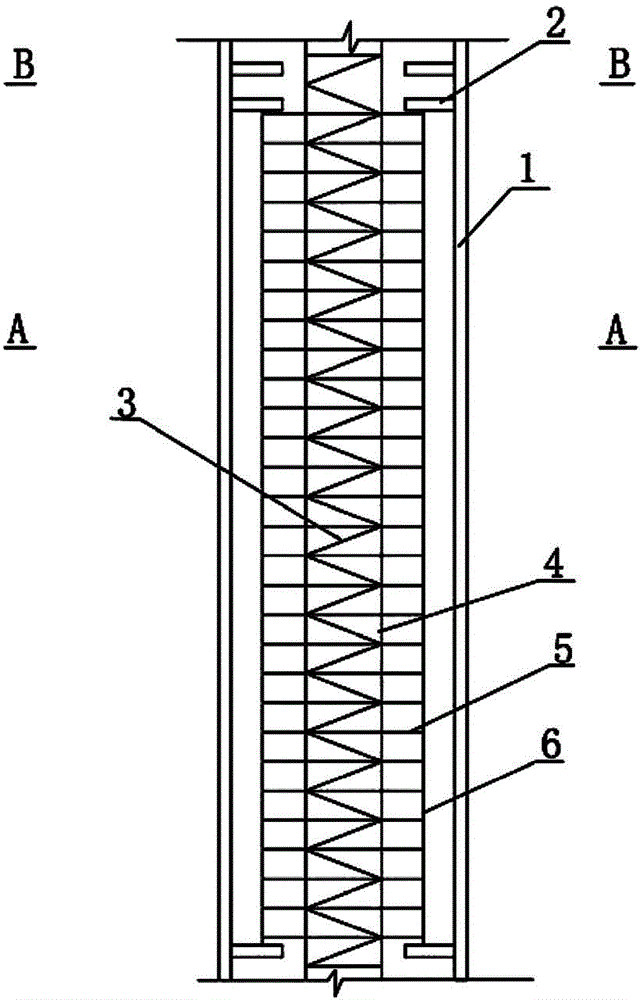
[0042] Embodiment one sees image 3 , Figure 4 and Figure 5 , is a multi-cavity steel pipe concrete wall with built-in prefabricated semi-continuous steel cages, including a steel frame with an aspect ratio greater than or equal to 3 and a continuous steel cage prefabricated with intermittent steel cages inside; the internal prefabricated intermittent steel cages The steel frame is a whole composed of intermittent steel cages, giant steel frames and anchors 8; the inside of the giant steel frame is divided into several cavities by horizontal vertical partitions 9, and each cavity is arranged at intervals along the height direction. Transverse partitions 2, the intermittent reinforcement cages are located between adjacent horizontal partitions 2, which are integrated with the inner wall of the giant steel frame through tie pieces 8; the continuous reinforcement cages are arranged along the length of the cavity , there is a hole in the middle of the transverse partition plat...


PUM


Abstract

The invention relates to a multi-cavity concrete-filled steel tubular wall with internal pre-machined semi-continuous reinforcement cages and a construction method. The multi-cavity concrete-filled steel tubular wall comprises a steel frame and a continuous reinforcement cage; discontinuous reinforcement cages are prefabricated in the steel frame; the length-to-width ratio of the steel frame is more than or equal to 3; the steel frame in which the discontinuous reinforcement cages are prefabricated is a whole consisting of the discontinuous reinforcement cages, a giant steel frame and tying parts; the giant steel frame is internally divided into a plurality of cavities by transverse vertical partition plates; transverse partition plates are arranged at intervals along the height direction in each cavity; the discontinuous reinforcement cages are positioned between the adjacent transverse partition plates, and are integrally connected with the inner wall of the giant steel frame through the tying parts; the continuous reinforcement cage is arranged in a full-length manner along the lengths of the cavities; holes through which the continuous reinforcement cage penetrate are formed in the middle parts of the transverse partition plates. According to the multi-cavity concrete-filled steel tubular wall and the construction method, the technical problems of weak compressive strength and shear strength and poor fire resistance of an ultra-long giant steel plate wall structure are solved, and the multi-cavity concrete-filled steel tubular wall and the construction method can be widely applied to a super high-rise large-span structure.

Description

technical field [0001] The invention relates to a steel plate shear wall and a construction method thereof, in particular to a multi-cavity steel pipe concrete wall with a built-in preprocessed semi-continuous reinforcement cage and a construction method thereof. Background technique [0002] With the increasing scale of urban buildings and the requirements of anti-seismic technology, the application of steel plate shear walls is increasing. The commonly used steel plate shear walls are wrapped with steel frames and poured concrete inside. However, there are some problems in this structural form. For example, concrete has the problem of shrinkage and creep, especially for large-scale steel plate shear walls. After the concrete with a large internal volume shrinks, there are micro-cracks between the steel plate and the concrete, which may cause the concrete and steel plate to be unable to bear the force at the same time. force effect. [0003] In order to solve the above pr...

Claims


Application Information

Patent Timeline
Patent Type & Authority Applications(China)
IPC IPC(8): E04B2/86
Inventor 姚攀峰
Owner 姚攀峰
Why Eureka
Try Eureka