
Drilling and blasting vehicle for tunnel excavation construction integrated with rotating and translation functions

A technology of tunnel excavation and integration, which is applied in the direction of tunnels, drilling with explosives, and drilling equipment. It can solve the problems of long time consumption, large manpower and material resources, and affecting the tunnel construction period, so as to achieve convenient movement, save construction time, The effect of high practical value

Inactive Publication Date: 2015-06-03
XIAN ZHONGZHI HUIZE PHOTOELECTRIC TECH
View PDF0 Cites 2 Cited by
  • Summary
  • Abstract
  • Description
  • Claims
  • Application Information

AI Technical Summary

Problems solved by technology

Nowadays, when blasting is carried out in the process of tunnel excavation, the hole position of each blasthole is generally determined by measuring tools, and then the blastholes are opened one by one in the surrounding rock by manual drilling rigs or drilling equipment; And after the opening of the blastholes is completed, the prefabricated explosives are manually put into each blasthole, which requires a lot of manpower and material resources, and takes a long time, which affects the tunnel construction period.

Method used


Image

  • Drilling and blasting vehicle for tunnel excavation construction integrated with rotating and translation functions
  • Drilling and blasting vehicle for tunnel excavation construction integrated with rotating and translation functions

Examples


Embodiment Construction

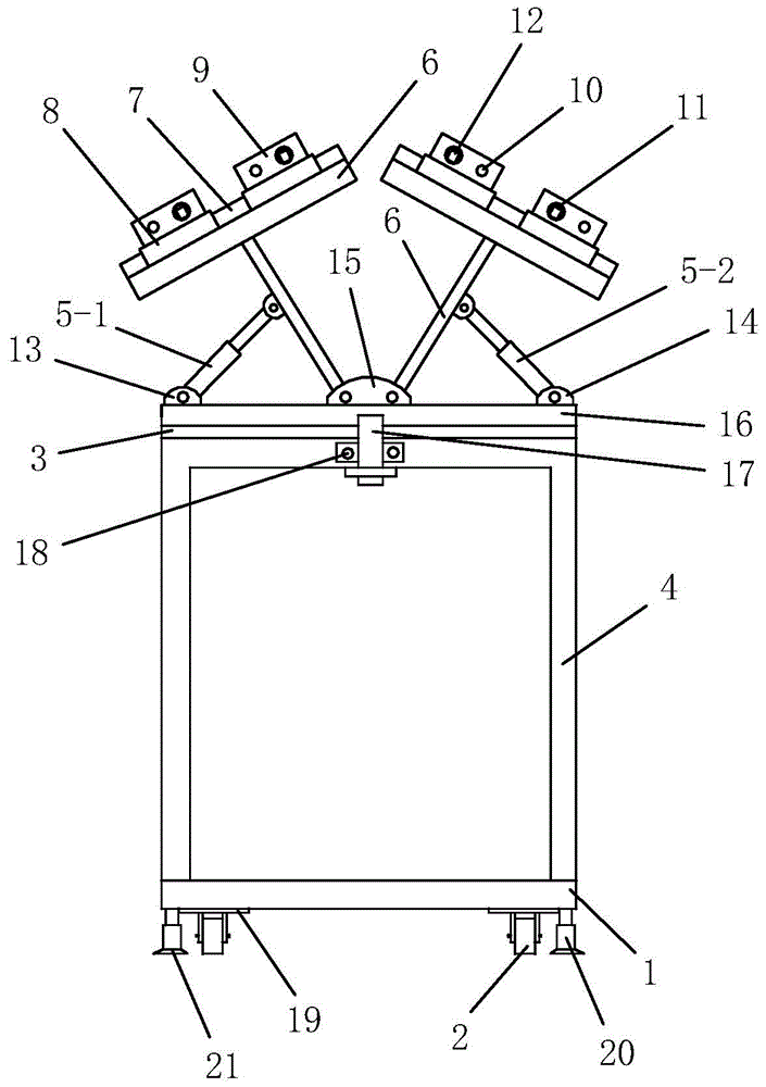
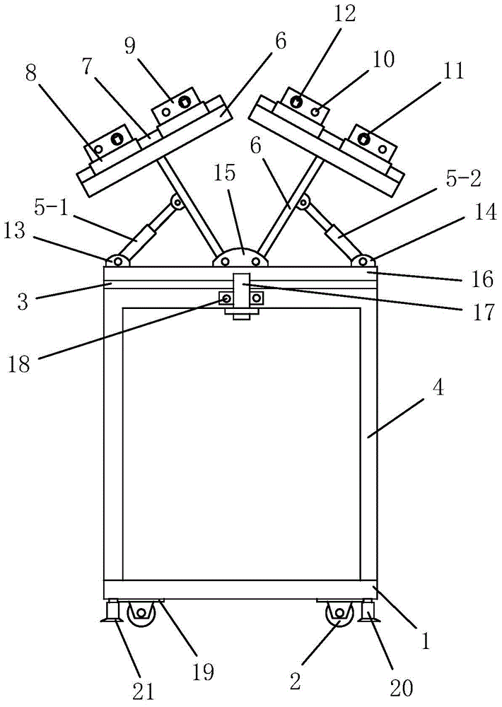
[0024] Such as figure 1 , figure 2 As shown, the present invention includes a section steel chassis 1 welded by a plurality of section steel rods and arranged horizontally, a vertical vehicle frame 4 installed on the section steel chassis 1, and a horizontal slide plate 3 installed on the vertical vehicle frame 4 , the horizontal turntable 16 that is installed on the horizontal slide plate 3, two hydraulic cylinders that are all installed on the horizontal turntable 16 and two swinging rock drilling blasting mechanisms that are all installed on the horizontal turntable 16. The two hydraulic cylinders are respectively the left side hydraulic cylinder 5-1 on the left side above the vertical vehicle frame 4 and the right side hydraulic cylinder 5-2 on the right side above the vertical vehicle frame 4, and the two swing type The rock-drilling and blasting mechanisms are respectively a swing-type rock-drilling and blasting mechanism 1 driven by the left hydraulic cylinder 5-1 to ...


PUM


Abstract

The invention discloses a drilling and blasting vehicle for tunnel excavation construction integrated with rotating and translation functions. The drilling and blasting vehicle comprises a steel section chassis, a vertical frame, a horizontal sliding plate, a horizontal rotary table, two hydraulic cylinders and two oscillating drilling and blasting mechanisms, wherein the two hydraulic cylinders are respectively a left hydraulic cylinder and a right hydraulic cylinder, the two oscillating drilling and blasting mechanisms are respectively a first oscillating drilling and blasting mechanism and a second oscillating drilling and blasting mechanism, the first oscillating drilling and blasting mechanism is driven to swing leftwards and rightwards by the left hydraulic cylinder and the second oscillating drilling and blasting mechanism is driven to swing leftwards and rightwards by the right hydraulic cylinder; the bottom of the steel section chassis is provided with a plurality of rotary chassis and a plurality of support hydraulic cylinders, travelling wheels are arranged on the rotary chassis and the rotary chassis can drive the travelling wheels to rotate leftwards and rightwards on a horizontal plane, and the support hydraulic cylinders are used for supporting the vertical frame in the process of rotating the plurality of travelling wheels leftwards and rightwards. The drilling and blasting vehicle provided by the invention is simple in structure, reasonable in design, convenient to use and operate and good in using effect, and the process of forming a plurality of blast-holes and feeding explosives can be completed conveniently and quickly; furthermore, the vehicle body has the functions of rotating and translating longitudinally and transversely.

Description

technical field [0001] The invention belongs to the technical field of tunnel blasting construction, and in particular relates to a rock drilling and blasting vehicle for tunnel excavation construction which integrates the functions of rotation and translation. Background technique [0002] In the process of tunnel excavation, most of them need to be blasted first, and rock drilling and blasting construction is an important tunnel blasting construction method. In actual rock drilling and blasting construction, it is often necessary to open multiple blasting holes on the blasting surface, and then configure the explosive package according to the pre-designed blasting parameters and put them into each blasting hole, and then detonate to complete the blasting construction. Nowadays, when blasting is carried out in the process of tunnel excavation, the hole position of each blasthole is generally determined by measuring tools, and then the blastholes are opened one by one in the...

Claims


Application Information

Patent Timeline
IPC IPC(8): E21B7/02E21D9/00
CPCE21B7/021E21B7/007E21D9/00
Inventor 侯鹏
Owner XIAN ZHONGZHI HUIZE PHOTOELECTRIC TECH
Learn More