Testing device for measuring lateral soil resistance of pipeline

A technology for measuring pipelines and test devices, used in measuring devices, force/torque/work measuring instruments, instruments, etc., can solve the problems of complex operation, large axial friction of bearing housing, and non-repeatability of force measuring system. The effect of saving test materials and easy operation

Inactive Publication Date: 2015-06-03
TIANJIN UNIV
View PDF7 Cites 4 Cited by
  • Summary
  • Abstract
  • Description
  • Claims
  • Application Information

AI Technical Summary

Problems solved by technology

But this device still has the following problems: (1) the test pipeline in the device cannot be lifted freely during the lateral movement process, because the bearing seat is used in the patent to realize the lifting of the test pipeline, but the axial friction of the bearing seat is relatively large, It has a great influence on the lifting of the test pipeline; (2) the device cannot adjust the weight of the test pipeline, and one test pipeline can only simulate one situation; (3) the device cannot measure the weight of the test pipeline during the lateral movement. Vertical displacement; (4) The force measuring system of the device is not repeatable. When replacing a test pipe, it is necessary to re-paste the strain gauge, and the operation is more complicated

Method used


Image

  • Testing device for measuring lateral soil resistance of pipeline
  • Testing device for measuring lateral soil resistance of pipeline
  • Testing device for measuring lateral soil resistance of pipeline

Examples


Embodiment Construction

[0029] The present invention will be described in detail below in conjunction with the accompanying drawings and embodiments.

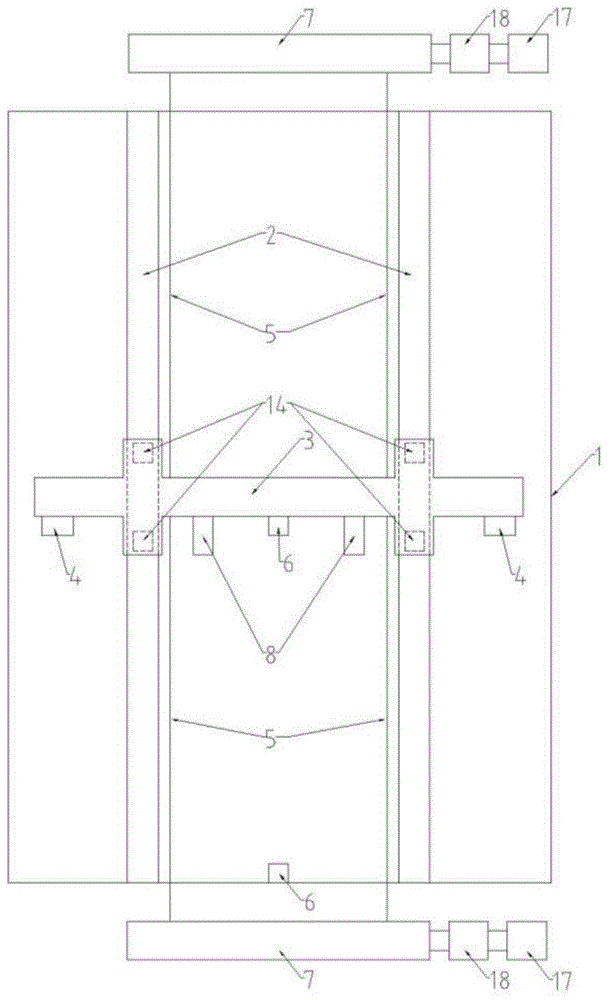
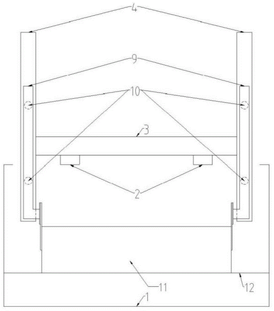
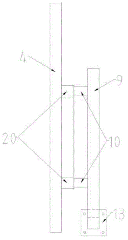
[0030] 1. The pipeline-soil interaction test device of the present invention mainly includes: soil tank 1, horizontal trolley 3, vertical trolley, force measuring system, displacement measuring system, pipeline weight adjustment system, test pipeline 11 and vertical bar 9 connection system , several parts of the power system.

[0031] 2. The soil tank 1 is a cuboid hollow structure with its surroundings closed and its top open. Planks of a certain thickness are laid on the side walls around the soil tank, and the top of the soil tank 1 is open. Two parallel horizontal linear guide rails 2 are arranged along the length direction of the soil tank 1 , and two sliders 14 are arranged on each horizontal linear guide rail 2 . The soil tank 1 is preset with a certain depth of horizontal soil for simulating a flat seabed, or preset with a certain depth of u...


PUM


Abstract

The invention relates to a testing device for measuring lateral soil resistance of a pipeline. The testing device comprises a soil groove (1), two horizontal linear guide rails (2), a horizontal trolley (3), vertical linear guide rails (4), two vertical rods (9), a force measuring system, a displacement measuring system, a pipeline weight regulating system and a power system, wherein the horizontal linear guide rails (2) are arranged along the length direction of the soil groove (1); sliding blocks (14) which are used for fixing the horizontal trolley (3) are arranged on the horizontal linear guide rails (2); the horizontal trolley (3) is fixedly provided with the two vertical linear guide rails (4) which are respectively provided with two sliding blocks, each sliding block (20) is provided with a tension and pressure sensor (10), and the tension and pressure sensors (10) are fixedly connected with the vertical rods (9); the bottom ends of the two vertical rods (9) are respectively and fixedly connected with the two ends of a test pipeline (11). According to the testing device disclosed by the invention, the measured soil resistance is enabled to more approach the stress of a seabed pipeline under a real state.

Description

Technical field [0001] The invention belongs to the technical field of submarine pipeline testing, and relates to a pipeline-soil interaction test device. Background technique [0002] In recent years, offshore oil and gas engineering has gradually developed into the deep sea. The normal operation of submarine pipelines is an important guarantee for deep-sea oil and gas development, and deep-sea submarine pipelines are generally placed bare on the surface of the seabed or partially buried. Under the action of high temperature and high pressure inside the pipe, the pipe placed on the surface of the seabed will buckle laterally. Excessive lateral movement will cause the local stress to exceed the yield limit, resulting in damage to the pipe structure and causing major engineering accidents. [0003] At present, in the theoretical research and numerical simulation of the lateral buckling of submarine pipelines, the Coulomb friction model is used for the soil resistance of the ...

Claims


Application Information

Patent Timeline
Patent Type & Authority Applications(China)
IPC IPC(8): G01L5/00
Inventor 唐友刚王臻魁冯浩
Owner TIANJIN UNIV
Why Eureka
Try Eureka