
car roof rack

A car roof and material rack technology, which is applied in the direction of motor vehicles, transportation and packaging, etc., can solve the problems of high requirements on the shape of power-assisted machinery and the inconvenience of picking up parts from the car roof material rack, and achieve the effect of optimizing the structure

Inactive Publication Date: 2019-06-28
ANHUI JIANGHUAI AUTOMOBILE GRP CORP LTD
View PDF6 Cites 0 Cited by
  • Summary
  • Abstract
  • Description
  • Claims
  • Application Information

AI Technical Summary

Problems solved by technology

[0006] The purpose of the present invention is to provide a car roof material rack to solve the problems of inconvenient picking of the car roof material rack and high requirements on the shape of the power booster

Method used


Image

  • car roof rack
  • car roof rack
  • car roof rack

Examples


Embodiment Construction

[0035] The technical solution of the present invention is described in detail below through the examples, and the following examples are only exemplary and can only be used to explain and illustrate the technical solution of the present invention, rather than being interpreted as a limitation to the technical solution of the present invention.

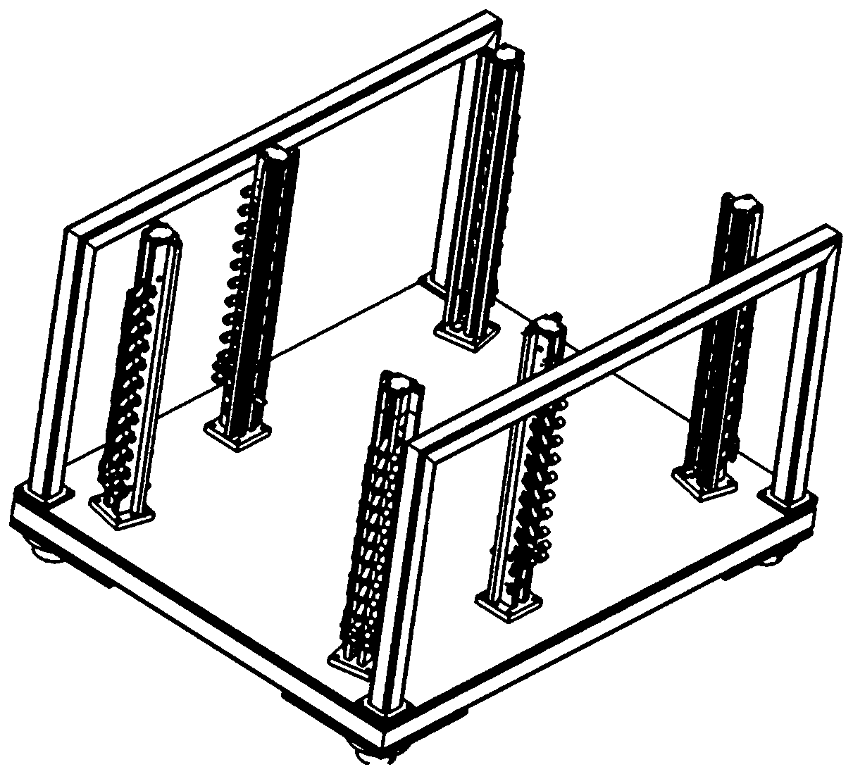
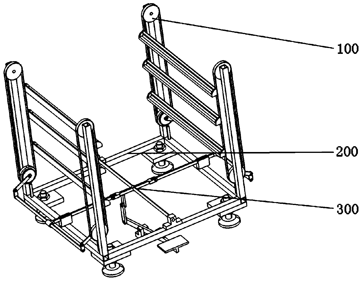
[0036] Such as figure 2 As shown, this application is composed of three horizontal blocks, and the external force drives the driven system 100 to rotate through the transmission system 300, so that the top cover placed in this application is gradually raised, and the purpose of always taking parts at the top of the material rack is achieved.

[0037] Such as Figure 5 As shown, the driven system 100 shares two sets, which are left-right symmetrical mechanisms, and each set itself is also a self-symmetrical structure. The driven system includes a left driven system, a right driven system and a roof support 103;

[0038] The left driv...


PUM


Abstract

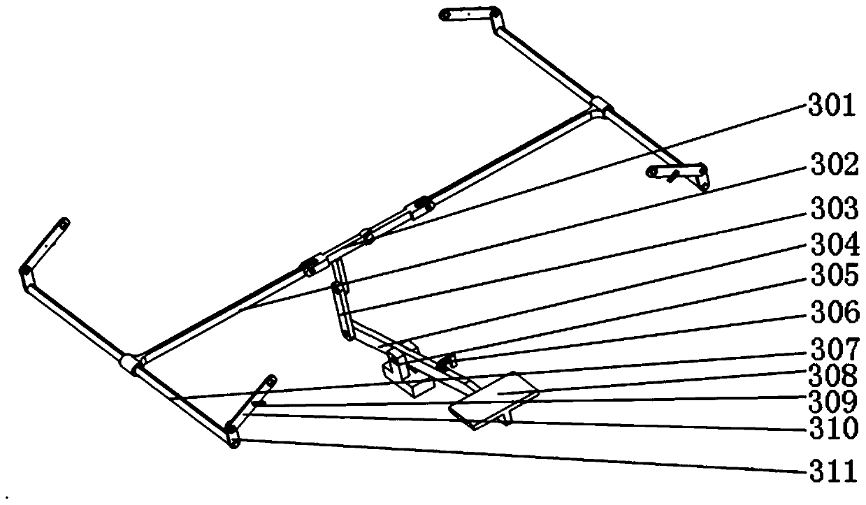
The invention relates to an automobile roof rack, which comprises a driven system, a support system and a drive system. The driven system is movably connected with the support system; the drive system is rotatably connected with the driven system and the support system; the driven system comprises a left driven system, a right driven system and a roof support; the support system comprises a bottom frame, four vertical supports; brake rods, brake blocks, sliding chute blocks, support legs, a rotary support rod and a rotary rod installation bases; and the drive system comprises a rotary rod, a first left rotary rod, a first right rotary rod, a support plate, a starting plate, a starting plate support seat, a spring, a second left rotary rod, a second right rotary rod, a pedal, a movable rotary block, first adapter plates and second adapter plates. According to the technical scheme, through the drive system and the two sets of driven systems, a structure of the rack is optimized, the circulating motion in the rack is realized, workpieces are taken from the topmost end of the rack, and the roof is lifted up freely.

Description

technical field [0001] The technical solution belongs to the technical field of automobile production line accessories, in particular to a material rack for an automobile roof cover. Background technique [0002] The car body is welded step by step from various types of small parts. In order to ensure the stability and reliability of the welding assembly formed after welding, special auxiliary tooling is designed to ensure the welding process. Auxiliary tooling at various levels must involve material circulation, and the efficiency and precision stability of the material circulation process are issues that need to be focused on in this field. [0003] Especially the top cover of the car has the characteristics of large area, soft material and high surface requirements. It is generally necessary to use power-assisted manipulators, suction cup spreaders or robot grippers to pick and place during the transfer process. [0004] In the prior art, the structure of the top cover r...

Claims


Application Information

Patent Timeline
Patent Type & Authority Patents(China)
IPC IPC(8): B62D65/18
CPCB62D65/18
Inventor 赵瑞汪小霞王宾
Owner ANHUI JIANGHUAI AUTOMOBILE GRP CORP LTD
Learn More