Axial vibration power-type piezoelectric ceramic transformer

A piezoelectric ceramic, axial vibration technology, applied in piezoelectric/electrostrictive/magnetostrictive devices, circuits, piezoelectric effect/electrostrictive or magnetostrictive motors, etc., can solve the problem of piezoelectric ceramics. Transformer performance, piezoelectric ceramic transformer overheating, weak thermal conductivity, etc.

Inactive Publication Date: 2015-06-03
SHAANXI NORMAL UNIV
View PDF4 Cites 2 Cited by
  • Summary
  • Abstract
  • Description
  • Claims
  • Application Information

AI Technical Summary

Problems solved by technology

Traditional piezoelectric ceramic transformers are basically directly coupled by the input piezoelectric ceramic element and the output piezoelectric ceramic element. Due to the weak thermal conductivity

Method used


Image

  • Axial vibration power-type piezoelectric ceramic transformer
  • Axial vibration power-type piezoelectric ceramic transformer
  • Axial vibration power-type piezoelectric ceramic transformer

Examples


Embodiment 1

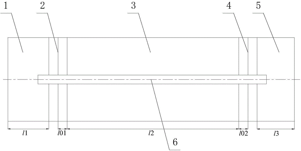
[0039] The first metal cylinder 1, the second metal cylinder 3 and the third metal cylinder 5 are all made of duralumin material, and their radii are equal to R respectively. 1 =R 2 =R 3 =0.01m, l 1 = l 2 = l 3 =0.02m; input the radius r of piezoelectric ceramic body 2 1 = 0.01m, which is composed of 2 thickness l 01 = 0.006m piezoelectric ceramic sheets are laminated, and the radius r of the output piezoelectric ceramic body 4 2 = 0.01m, which is composed of 2 thickness l 02 = 0.006m piezoelectric ceramic sheets laminated; where l 1 +l 2 +l 3 +2l 01 +2l 02 >4R 1 .

[0040] When the load resistance of the transformer is 50 ohms, using the resonance frequency equation and transformation ratio formula obtained in the present invention, the resonance frequency of the transformer is 25656 Hz, the anti-resonance frequency is 27458 Hz, and the transformation ratio is 1.0002.

Embodiment 2

[0042] The first metal cylinder 1, the second metal cylinder 3 and the third metal cylinder 5 are all made of duralumin material, and their radii are equal to R respectively. 1 =R 2 =R 3 =0.01m, l 1 = l 2 =0.04m, l 3 =0.01m; input the radius r of piezoelectric ceramic body 2 1 = 0.01m, which is composed of 2 thickness l 01 = 0.006m piezoelectric ceramic sheets are laminated, and the radius r of the output piezoelectric ceramic body 4 2 = 0.01m, which is composed of 2 thickness l 02 = 0.006m piezoelectric ceramic sheets are laminated; l 1 +l 2 +l 3 +2l 01 +2l 02 >4R 1 .

[0043] When the load resistance of the transformer is 50 ohms, using the resonance frequency equation and transformation ratio formula obtained in the present invention, the resonance frequency of the transformer is 19071 Hz, the anti-resonance frequency is 20283 Hz, and the transformation ratio is 1.728.

Embodiment 3

[0045] The first metal cylinder 1, the second metal cylinder 3 and the third metal cylinder 5 are all made of duralumin material, and their radii are equal to R respectively. 1 =R 2 =R 3 =0.01m, l 1 = l 2 =0.01m, l 3 =0.04m; input the radius r of piezoelectric ceramic body 2 1 = 0.01m, which is composed of 2 thickness l 01 = 0.006m piezoelectric ceramic sheets are laminated, and the radius r of the output piezoelectric ceramic body 4 2 = 0.01m, which is composed of 2 thickness l 02 = 0.006m piezoelectric ceramic sheets are laminated; l 1 +l 2 +l 3 +2l 01 +2l 02 >4R 1 .

[0046] When the load resistance of the transformer is 50 ohms, using the resonance frequency equation and transformation ratio formula obtained in the present invention, the resonance frequency of the transformer is 26211 Hz, the anti-resonance frequency is 27178 Hz, and the transformation ratio is 0.588.


PUM

PropertyMeasurementUnit
Resonance frequencyaaaaaaaaaa
Thicknessaaaaaaaaaa
Resonance frequencyaaaaaaaaaa

Abstract

The invention relates to an axial vibration power-type piezoelectric ceramic transformer. The axial vibration power-type piezoelectric ceramic transformer comprises an input piezoelectric ceramic body and an output piezoelectric ceramic body, wherein a metal cylinder is arranged at each of the positions between the input piezoelectric ceramic body and the output piezoelectric ceramic body, outside the input piezoelectric ceramic body and outside the output piezoelectric ceramic body. According to the axial vibration power-type piezoelectric ceramic transformer, the metal cylinders have the effects of effectively improving the radiating effect of the transformer, increasing the power capacity of the transformer, and greatly improving the electromechanical performance of the transformer; meanwhile, the working frequency of the novel piezoelectric ceramic transformer can be changed very conveniently by changing the geometric sizes of the metal cylinders in the piezoelectric ceramic transformer, so that the piezoelectric ceramic transformer can be adapted to different application places; therefore, the cost can also be reduced.

Description

technical field [0001] The invention belongs to the technical field of piezoelectric transformers, in particular to an axial vibration power type piezoelectric ceramic transformer. Background technique [0002] At present, the traditional way to increase or decrease the alternating voltage is to use an electromagnetic transformer. An electromagnetic transformer is mainly composed of an iron core and a coil surrounding the iron core. In an electromagnetic transformer, the primary and secondary coils are electromagnetically coupled through a magnetic core. In some electrical and high-power electronic applications, large electromagnetic transformers are very effective. However, with the development of science and technology and the miniaturization of electronic devices, many applications in the electronics industry require high-efficiency components with small dimensions, so the demand for small high-efficiency transformers is increasing. Due to its inherent reasons, such as...

Claims


Application Information

Patent Timeline
IPC IPC(8): H01L41/113H01L41/053H01L41/083H02N2/00
Inventor 林书玉
Owner SHAANXI NORMAL UNIV
Why Eureka
Try Eureka