Overcurrent protection device

An overcurrent and current technology, applied in circuit devices, circuit devices, circuit thermal devices, etc., can solve the problems of low thermal conductivity and low temperature detection accuracy, and achieve the effect of saving space

Inactive Publication Date: 2015-06-03
KYOCERA DOCUMENT SOLUTIONS INC
View PDF5 Cites 1 Cited by
  • Summary
  • Abstract
  • Description
  • Claims
  • Application Information

AI Technical Summary

Problems solved by technology

[0008] However, compared with the thermal conductivity of the circuit pattern material, the thermal conductivity of the circuit board material is generally very low, for example, about 1 / 2000.
In this way, even if the thermistor is installed in the part where there is no circuit pattern, almost no heat will be transferred, so the temperature detection accuracy is very low

Method used


Image

  • Overcurrent protection device
  • Overcurrent protection device
  • Overcurrent protection device

Examples


Embodiment approach

[0024] A first embodiment of the present invention will be specifically described below with reference to the drawings. The overcurrent prevention device of the present invention is suitable for devices that drive components such as DC power generated from supplied commercial power supply, and use the DC power to increase current fluctuations or generate momentary huge currents like a motor or the like.

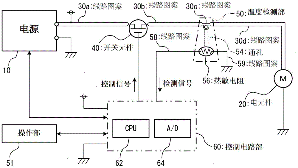
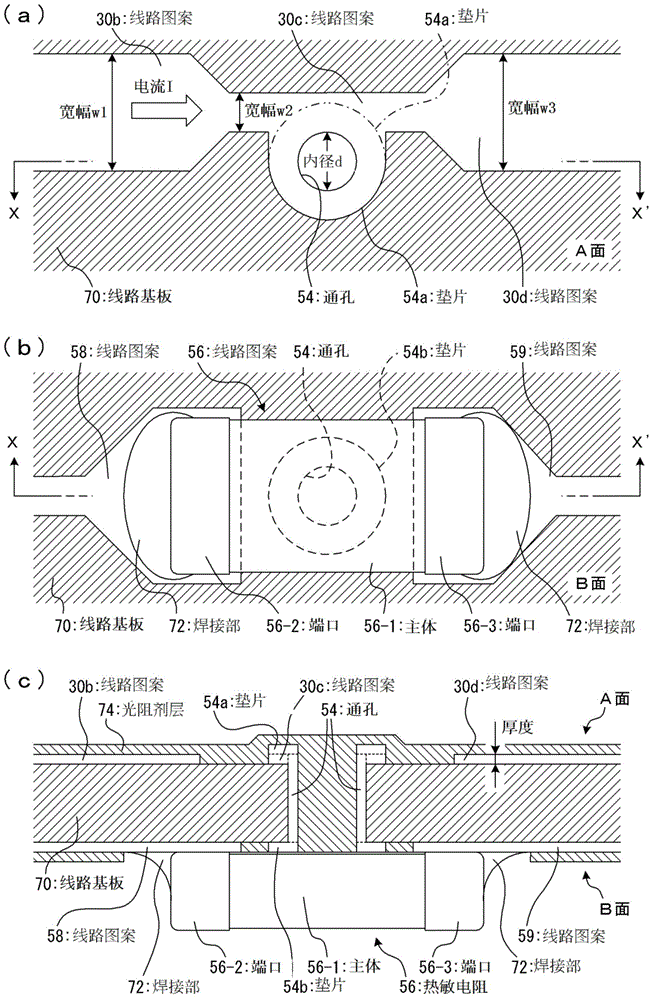
[0025] Such as figure 1 As shown, the present embodiment also utilizes the direct current outputted by the power supply 10 to drive a load such as a motor, that is, a circuit of the electric element 20, but between the power supply 10 and the electric element 20, circuit patterns 30a and 30b (first circuit circuit), The wiring pattern 30c (heating wiring portion) and the wiring pattern 30d (first wiring circuit) are connected. It is assumed that the line patterns 30a, 30b, 30c, 30d will pass a relatively large current, so even in figure 1 On the circuit diagram of the circu...

no. 2 example

[0054] In the first embodiment described above, the circuit board through which current flows is formed with a narrow circuit pattern 30c, and the circuit pattern 30c is used as a heat source to monitor overcurrent. However, it is also possible to form a structure that directly monitors the heat generation of electrical components such as transistors, FETs, semiconductor components, and ICs (Integrated Circuit, integrated circuits).

[0055] Below, use Figure 5 (a) and Figure 5 (b) Describes a structural example in which overcurrent is prevented by monitoring heat generation of electrical components. In addition, in Figure 5 (a) and Figure 5 (b), same as figure 1 or figure 2 (a)~ figure 2 Parts corresponding to the respective parts shown in (c) are denoted by common symbols, and detailed explanations are omitted.

[0056] exist Figure 5 In (a), the direct current output from the power source 10 is supplied to the electric element 20a via the wiring pattern 30a a...

no. 3 example

[0064] Also, use Figure 6 (a) and Figure 6 (b) Another structural example for preventing overcurrent by monitoring heat generation of electrical components is described. Should Figure 6 (a) and Figure 6 (b) will also be the same as figure 1 or figure 2 (a)~ figure 2 (c), Figure 5 (a), Figure 5 Parts corresponding to the respective parts shown in (b) are given common symbols, and detailed description is omitted.

[0065] exist Figure 6 In (a), the direct current output from the power source 10 is supplied to the electric element 20b via the wiring pattern 30a and the switching element 40, the wiring pattern 30b, and the metal terminal 20b-2. The electrical element 20b is also a CPU that generates heat when a large current flows when controlling high-speed processing, and a drive element that generates heat when controlling the current supplied to a load.

[0066] The temperature detection unit 50b is composed of a through hole 54, a thermistor 56, wiring patt...


PUM


Abstract

An overcurrent protection device satisfactorily detects overcurrent without adding complicated component or occupying large space. Penetration member penetrates board face A having a first wiring circuit and face B with a second one, transmitting heat from face A to B. Connection/disconnection part is inserted into first wiring circuit, switching current to heat generation part for generating heat with current, formed in portion of first circuit, continued with one end of penetration member. Temperature detection member disposed near or abutted against other end of penetration member on face B detects transmitted heat, outputting signal. Control part controls connection/disconnection part on signal. Heat generation part is narrower than width w1 not generating heat in steady state, having width w2 to raise temperature upon overcurrent, and being sandwiched between patterns with width w1. Control part turns off current with heat generation part temperature raised to or above prescribed threshold.

Description

technical field [0001] The present invention relates to a device capable of preventing overcurrent from flowing into a circuit pattern and components arranged on a circuit board. Background technique [0002] In recent years, people have very high requirements for the miniaturization of circuit boards, and correspondingly, electronic accessories and the like also show a trend of miniaturization. However, the miniaturization of electronic accessories does not mean that the power used will be reduced as much as possible, so it can be said that electronic accessories are more likely to generate heat. [0003] However, among electronic accessories, sometimes the operation is not smooth due to overheating, which will also affect related accessories, and may become the cause of some unexpected accidents. In order to prevent problems before they happen, one of the methods is to suppress excessive heat generation by preventing overcurrent. [0004] Conventionally, various methods ...

Claims


Application Information

Patent Timeline
Patent Type & Authority Applications(China)
IPC IPC(8): H02H3/08
CPCH02H3/085H05K1/0212H05K1/0265H05K2201/09727H05K2201/10151
Inventor 石堂纮平
Owner KYOCERA DOCUMENT SOLUTIONS INC
Why Eureka
Try Eureka