Electronic device and assembling method thereof

The technology of an electronic device and assembly method, which is applied in the direction of output power conversion device, electrical equipment shell/cabinet/drawer, circuit, etc., can solve the problem that power conversion device consumes a large amount of power, cannot effectively transmit heat energy, and has limited heat dissipation efficiency and other issues, to reduce the risk of thermal failure, save assembly time, and improve the effect of heat dissipation

Active Publication Date: 2015-06-03
DELTA ELECTRONICS SHANGHAI CO LTD
View PDF5 Cites 11 Cited by
  • Summary
  • Abstract
  • Description
  • Claims
  • Application Information

AI Technical Summary

Problems solved by technology

[0004] However, since the power conversion device consumes a large amount of electricity, these electronic components in the power conversion device generate a considerable amount of heat energy. In addition, these electronic components are not in contact with any physical objects, resulting in limited heat dissipation efficiency and cannot effecti

Method used


Image

  • Electronic device and assembling method thereof
  • Electronic device and assembling method thereof
  • Electronic device and assembling method thereof

Examples


no. 1 approach

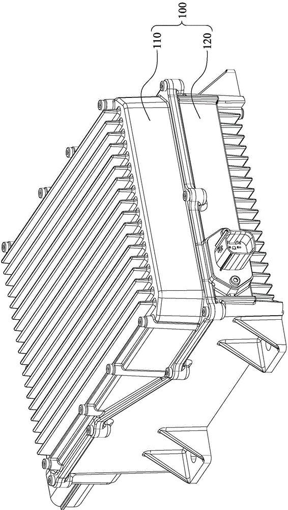
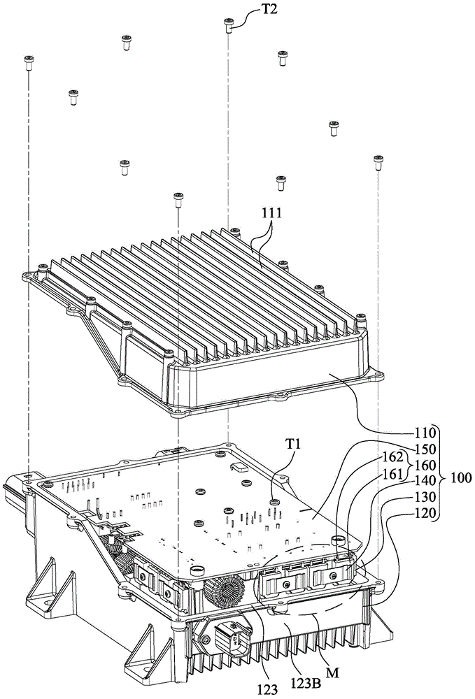
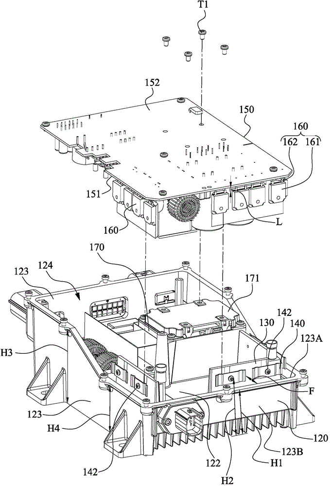
[0056] figure 1 A combined diagram of the electronic device 100 according to the first embodiment of the present invention is shown. figure 2 draw figure 1 partial exploded view. Such as figure 1 and figure 2 shown. An electronic device 100 includes a bottom case 120 , a heat dissipation component 130 , an elastic clip 140 , a wiring board 150 and at least one electronic component 160 (such as a transistor). The heat dissipation assembly 130 is located on the bottom case 120 . The elastic clip 140 is partially installed on the heat dissipation component 130 . Each electronic component 160 includes a body 161 and a plurality of pins 162 . Pins of the electronic component 160 are electrically connected to the wiring board 150 , and the body is clamped between the heat dissipation component 130 and the elastic clip 140 .

[0057] In this way, in the above-mentioned structure, the electronic components and the heat dissipation components are tightly bonded by the elastic...

no. 2 approach

[0072] Figure 5A A perspective view of the insulating pillar 180 according to the second embodiment of the present invention is shown. Figure 5B A cross-sectional exploded view of the wiring board 150 , the insulating support 180 and the heat dissipation component 130 is shown according to the second embodiment of the present invention. The insulating pillar 180 of the second embodiment can be used in the first embodiment. Such as Figure 5BIn order to maintain a fixed connection and electrical insulation between the wiring board 150 and the bottom case 120 , at least one insulating pillar 180 is further included between the wiring board 150 and the bottom case 120 . The insulating pillar 180 connects the heat dissipation component 130 and the distribution board 150 , physically fixes the heat dissipation component 130 and the distribution board 150 , and electrically insulates the heat dissipation component 130 and the distribution board 150 .

[0073] More specifically,...

no. 3 approach

[0077] Figure 6A An exploded view of the electronic device 101 according to the third embodiment of the present invention is shown. Figure 6B A combination diagram of the elastic clip 240 and the heat dissipation component 230 according to the third embodiment of the present invention is shown. Such as Figure 6A As shown, the electronic device 101 of the third embodiment is substantially the same as the electronic device 100 of the first embodiment, except that the appearance of the elastic clip 240 and the heat dissipation assembly 230 of the third embodiment are compared with those of the elastic clip 140 and the first embodiment. The appearance of the cooling assembly 130 is different. Specifically, the heat dissipation assembly 230 is an independent object, and is detachably assembled to the bottom case 120 . The heat dissipation assembly 230 includes two partial features, namely a heat dissipation block 231 and a base 232 . The heat dissipation block 231 of the loc...


PUM


Abstract

An electronic device includes a bottom case, an accommodation unit, an electromagnetic induction module, a heat-dissipating component, an elastic clip, a printed wiring board, and an electronic component. The accommodation unit is disposed on the bottom case. At least one portion of the electromagnetic induction module is disposed in the accommodation unit. The heat-dissipating component is disposed on the bottom case and is positioned separately from the accommodation unit. The elastic clip is partially mounted on the heat-dissipating component. The printed wiring board has a first surface and a second surface, and the first surface faces the accommodation unit. The electronic component includes a main body and pin feet. The pin feet are electrically connected to the printed wiring board, and the main body is clamped between the heat-dissipating component and the elastic clip.

Description

technical field [0001] The present invention relates to electronic devices, and in particular to an electronic device with a heat dissipation component and an assembly method thereof. Background technique [0002] Gasoline-electric hybrid vehicles or electric vehicles have the advantages of economy, energy saving, and environmental protection. Under the crisis of energy shortage, they have become the research and development focus of major car manufacturers. With the development of the automobile industry, the number of automobiles continues to increase, and the pressure of environmental pollution and energy shortage is becoming increasingly apparent. With the current shortage of oil resources in the world and the urgent situation of global warming, countries all over the world have listed energy conservation and environmental protection as the priority development direction of the future automobile industry. Electric vehicles, with their outstanding features of high effici...

Claims


Application Information

Patent Timeline
IPC IPC(8): H05K7/20
CPCH05K7/209Y10T29/49002Y10T29/49144H05K7/14322B60L1/00B60L7/00H01L23/29H02M3/00H05K3/328H05K5/00H05K5/0039H05K7/1432H05K7/20H05K7/20409Y02T90/12H05K2203/04
Inventor 陆兴先尤培艾刘钢章进法
Owner DELTA ELECTRONICS SHANGHAI CO LTD
Why Eureka
Try Eureka