Clocked voltage converter
A technology of voltage converter and synchronous voltage, which is applied in the direction of output power conversion devices, instruments, electric light sources, etc., and can solve the problems of high cost, large tolerance, and large circuit technology overhead
- Summary
- Abstract
- Description
- Claims
- Application Information
AI Technical Summary
Problems solved by technology
Method used
Image

Examples
Embodiment Construction
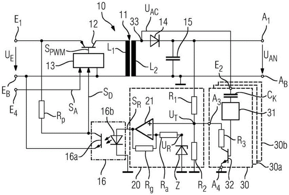
[0030] figure 1 is shown with the input voltage for U E The input terminal E 1 and galvanically isolated from it (electrically isolated) for multiple output voltages U An output terminal A 1 The circuit of adjustable synchronous voltage converter 10 . A synchronous voltage converter 10 operating as a DC voltage converter has on the input side and a primary winding L 1 and the secondary winding L 2 The primary side of the transformer 11 has a semiconductor switch 12 referred to below as a switching transistor. The switching transistor 12 is controlled by a pulse width modulator 13 hereinafter referred to as PWM means.
[0031] The transformer 11 arranged downstream of the switching transistor 12 performs the voltage conversion and the input E of the voltage converter 10 1 and output A 1 Potential isolation between. A rectifier 14 in the form of a series diode and a capacitor 15 connected in parallel for smoothing the pulsed or pulsating DC voltage generated by the diode ...
PUM
 Abstract
Description
Claims
Application Information
 - R&D
- Intellectual Property
- Life Sciences
- Materials
- Tech Scout
- Unparalleled Data Quality
- Higher Quality Content
- 60% Fewer Hallucinations
Browse by: Latest US Patents, China's latest patents, Technical Efficacy Thesaurus, Application Domain, Technology Topic, Popular Technical Reports.
© 2025 PatSnap. All rights reserved.Legal|Privacy policy|Modern Slavery Act Transparency Statement|Sitemap|About US| Contact US: help@patsnap.com