Automatic fertilizer stirring and applying device

A fertilization device and automatic stirring technology, applied in the field of automatic stirring and fertilizing devices, can solve the problems of manual fertilization, low work efficiency, long fertilization time, etc., so as to prolong the pure operation time of machines and tools, improve work efficiency and improve the efficiency of fertilization. The effect of efficiency

Active Publication Date: 2015-06-10
AGRI MACHINERY INST CHINESE TROPICAL ACAD OF SCI
View PDF5 Cites 3 Cited by
  • Summary
  • Abstract
  • Description
  • Claims
  • Application Information

AI Technical Summary

Problems solved by technology

[0003] However, fertilization, especially for some economic crops, still requires manual
The production of most of the sugarcane areas in my country still relies on human and livestock operations, and manual fertilizer application can only complete about 2 acres of work per person per day. There are weak functions of water and fertilizer retention, poor lodging resistance of sugarcane, high labor intensity and low work efficiency. Problems such as low utilization rate; fertilization of sugarcane generally implements mixed fertilization with different formulas according to different growth periods of sugarcane, that is, the application of mixed fertilizers containing different proportions of urea, phosphorus fertilizer, potassium fertilizer, etc. The existing machinery and equipment, mixed fertilizers and auxiliary labor for fertilization need 3 People usually gather in the field to stir and mix, manually shovel into the bag and then apply fertilizer, and the tractor loads fertilizer back and forth. It takes a long time to load fertilizer each time, requires a lot of auxiliary labor, and the work efficiency is low. Fertilization is about 20 acres of fields per day.

Method used


Image

  • Automatic fertilizer stirring and applying device
  • Automatic fertilizer stirring and applying device
  • Automatic fertilizer stirring and applying device

Examples


Embodiment

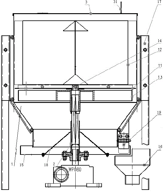
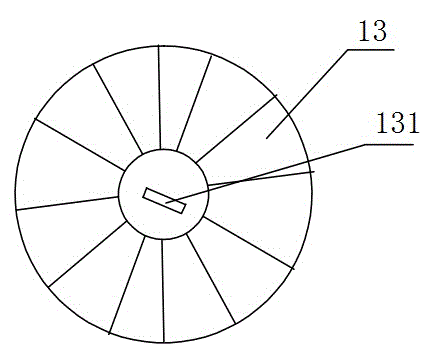
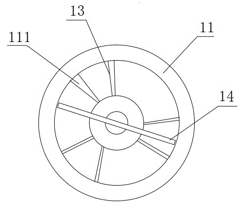
[0025] Such as Figures 1 to 3 Shown is the embodiment of the automatic stirring fertilization device of the present invention, and the fertilization device comprises fertilization tube 1 and the first leaking plate 11 that is placed in fertilization tube 1, and the first leaking plate 11 is matched with fertilization tube 1; Fertilization tube 1 and above the first drain plate 11 are provided with three isolation grids 12, and the three isolation grids 12 divide the fertilization cylinder 1 into three areas; the first drain plate 11 is in the three areas divided by the isolation grid 12 Both are provided with a material leakage port 111; the fertilization cylinder 1 is located under the first material leakage plate 11 and is provided with a rotatable impeller 13, and the impeller 13 is provided with a number of blades with spacing; Rod 14, stirring rod 14 is positioned at the top of the first leaking material plate 11 and is positioned at the below of barrier 12; The lower en...


PUM


Abstract

The invention relates to the technical field of fertilizer applying structures, in particular to an automatic fertilizer stirring and applying device. The automatic fertilizer stirring and applying device comprises a fertilizer applying barrel and a first leakage plate arranged in the fertilizer applying barrel. Three separation fences are arranged in the fertilizer applying barrel and located above the first leakage plate. The three separation fences divide the fertilizer applying barrel into three regions. The first leakage plate is provided with three leakage ports in the three regions divided by the three separation fences respectively. A rotatable impeller is arranged in the fertilizer applying barrel and located below the first leakage plate. The impeller is provided with a plurality of blades at intervals. A stirring rod mounted on the impeller is further arranged in the fertilizer applying barrel. The impeller is connected with a tray through a connecting shaft and drives the tray to rotate. The lower end of the fertilizer applying barrel is further provided with a discharge structure used for leaking out fertilizer. By the adoption of the automatic fertilizer stirring and applying device, a user just needs to pour three different kinds of fertilizer such as urea, phosphatic fertilizer and potash fertilizer into different fertilizer applying boxes, and the three different kinds of fertilizer including powdery fertilizer and granular fertilizer can be automatically blended.

Description

technical field [0001] The invention relates to the technical field of a fertilization structure, and more particularly, relates to an automatic stirring fertilization device. Background technique [0002] As a large agricultural province in my country, the planting, fertilization and harvesting of crops are very important. In the past, these steps needed to be completed manually, which was very time-consuming and laborious. In recent years, with the development of science and technology, the planting and harvesting of some crops have been gradually mechanized, reducing people's physical labor. [0003] But fertilization, especially the fertilization of some commercial crops, still needs manual work. The production of most of the sugarcane areas in my country still relies on human and livestock operations. Fertilizers are spread by hand. Each person can only complete about 2 acres of work per day. There are weak functions of water and fertilizer retention, poor lodging res...

Claims


Application Information

Patent Timeline
Patent Type & Authority Applications(China)
IPC IPC(8): A01C15/12
CPCY02P60/21
Inventor 董学虎张婷牛钊君李明韦丽娇黄敞
Owner AGRI MACHINERY INST CHINESE TROPICAL ACAD OF SCI
Why Eureka
Try Eureka