Solder tip production process
A production process and soldering iron tip technology, applied in the direction of soldering iron, manufacturing tools, metal processing equipment, etc., can solve the problems of harming human health, unstable quality, and sewage discharge, etc., and achieve labor saving, default process, and short production cycle Effect
- Summary
- Abstract
- Description
- Claims
- Application Information
AI Technical Summary
Benefits of technology
Problems solved by technology
Method used
Image
Examples
Embodiment 1
[0053]Embodiment 1 of the present invention provides a soldering iron tip production process, the soldering iron tip production process comprises:
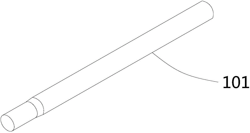
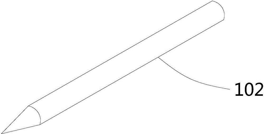
[0054] Copper mold blank 102 manufacturing steps: Copper raw material is made into copper blank 101, and one end thereof is processed into a tapered working end.
[0055] Copper billet iron sleeve fitting 104 processing steps:
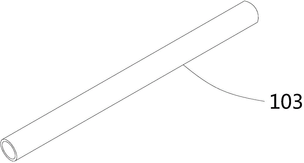
[0056] The iron sleeve 103 is placed outside the copper mold blank 102 and fixed to form a copper blank iron sleeve 104 .
[0057] A die is used to process one end of the iron sleeve 103 into a tapered shape that completely covers the working end of the copper mold blank 102 to form the head of the copper blank iron sleeve 104 .
[0058] Dimensional correction step: carry out dimensional correction to the body of the copper billet iron casing 104 to reach the standard size.
[0059] Surface treatment step: surface treatment is carried out on the copper billet iron casing piece 104 .
[0060] Thus, a sol...
Embodiment 2
[0063] Embodiment 2 of the present invention provides a soldering iron tip production process, the soldering iron tip production process includes all the technical features of the soldering iron tip production process provided in Embodiment 1, and the process steps of the soldering iron tip production process are as follows:
[0064] Manufacturing steps of the copper mold blank 102: straighten, position, and cut the copper disc material according to the product size requirements, and extrude it into a copper billet 101. For the structure of the copper billet 101, please refer to figure 1 . The size of the copper billet 101 is generally φ3.5mm-φ9.0mm, and the length is generally 35mm-100mm. This embodiment takes φ5.2mm and length 69mm as an example for specific description. Then utilize a lathe to turn one end of the copper blank 101 into a tapered shape, and turn the other end of the copper blank 101 into a chamfered position to form a copper mold blank 102. For the structure...
Embodiment 3
[0092] Embodiment 3 of the present invention provides a production process of a soldering iron tip. The difference between the production process of the soldering iron tip and the production process of the soldering iron tip provided in Embodiment 2 is that:
[0093] The production process of the soldering iron tip provided in Example 3 also includes a forming step, which is after the processing step of the copper billet iron sleeve 104, specifically, the forming step is after the dimension correction step.
[0094] Forming step: process the head into a horseshoe shape, a knife edge shape or a flat mouth shape. What the present embodiment adopts is that mechanical extrusion process is pressed the head into horseshoe shape, knife-edge shape or flat mouth shape.
[0095] It should be understood that after the size correction step, the body is already a straight cylindrical shape, and the head is processed into a horseshoe shape, a knife-edge shape or a flat mouth shape, so what ...
PUM
 Abstract
Description
Claims
Application Information
 - R&D
- Intellectual Property
- Life Sciences
- Materials
- Tech Scout
- Unparalleled Data Quality
- Higher Quality Content
- 60% Fewer Hallucinations
Browse by: Latest US Patents, China's latest patents, Technical Efficacy Thesaurus, Application Domain, Technology Topic, Popular Technical Reports.
© 2025 PatSnap. All rights reserved.Legal|Privacy policy|Modern Slavery Act Transparency Statement|Sitemap|About US| Contact US: help@patsnap.com


