Conical/cylindrical linear rollaway nest superfinishing equipment

A raceway and cylinder technology, applied in the field of conical/cylindrical linear raceway ultra-precision equipment, can solve problems such as insufficient guiding performance, dead center position, unstable swing, etc., to achieve stable and reliable workpiece conveying, and improve surface accuracy and quality. , the effect of avoiding collision damage

Active Publication Date: 2015-06-10
WUXI LANMA MACHINERY MFR
View PDF9 Cites 8 Cited by
  • Summary
  • Abstract
  • Description
  • Claims
  • Application Information

AI Technical Summary

Problems solved by technology

The existing conical/cylindrical linear raceway superfinishing equipment has the following problems: (1) The oscillating mechanism used on the superfinishing machine tool is connected with a rotating shaft on the motor shaft through a coupling, and the rotating shaft Two symmetrical balance weights are installed on both sides of the bottom with a crank through the balance wheel. A ram is installed under the rotating shaft with a crank, a slide seat and its driving wheel, and an oilstone clip is installed at the lower end of the ram. This traditional The oscillating mechanism of the ultra-precision equipment adopts the crank-connecting rod mechanism, which is prone to problems such as inaccurate eccentricity, dead point position, easy breakage of the connecting rod, and difficulty in keeping the crank on the same level, so it is impossible to super-precision the bearing raceway. The logarithmic curve cannot meet the grinding requirements of high-precision surfaces; (2) The raceway super-precision swing head and rib super-fine swing head used are single-piston-guided or single-piston plus a guide-rod-guided. All of these me

Method used


Image

  • Conical/cylindrical linear rollaway nest superfinishing equipment
  • Conical/cylindrical linear rollaway nest superfinishing equipment
  • Conical/cylindrical linear rollaway nest superfinishing equipment

Examples


Embodiment Construction

[0034] The preferred embodiments of the present invention will be described below in conjunction with the accompanying drawings. It should be understood that the preferred embodiments described here are only used to illustrate and explain the present invention, and are not intended to limit the present invention.

[0035] like figure 1 As shown,.

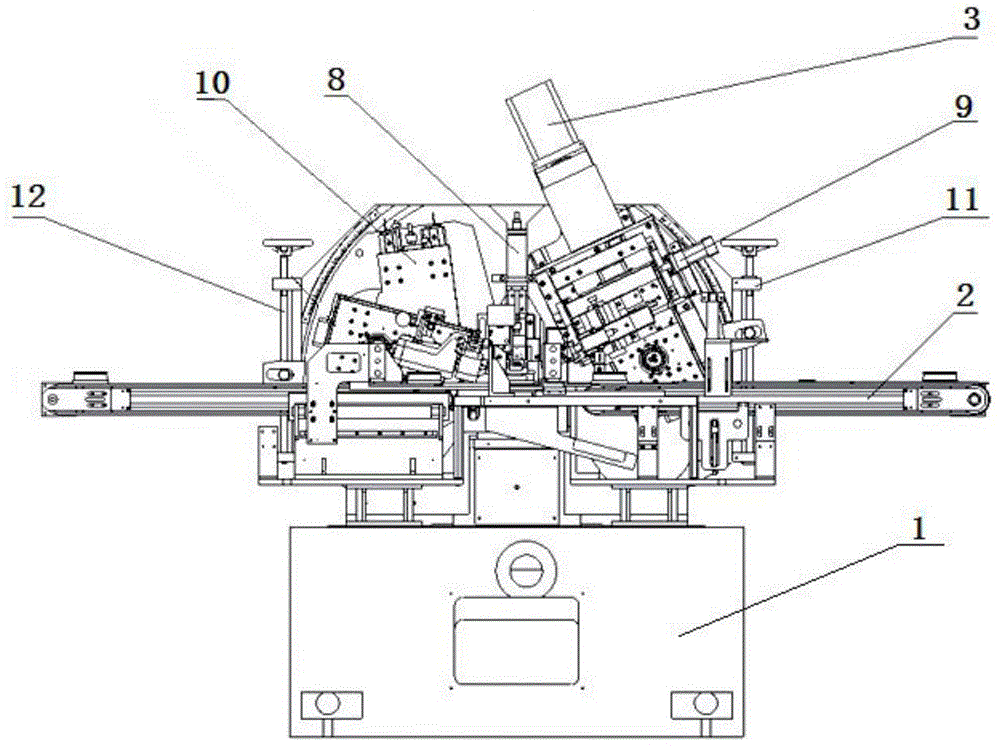
[0036] The present invention is a conical / cylindrical linear raceway ultra-precision equipment, including an operation table 1 and a loading and unloading conveying mechanism 2 erected on the operation table 1, and the operation table 1 is also provided with a large reciprocating small oscillation mechanism 3 and a raceway Super precision swing head 4 and sidewall super precision swing head 5, in which:

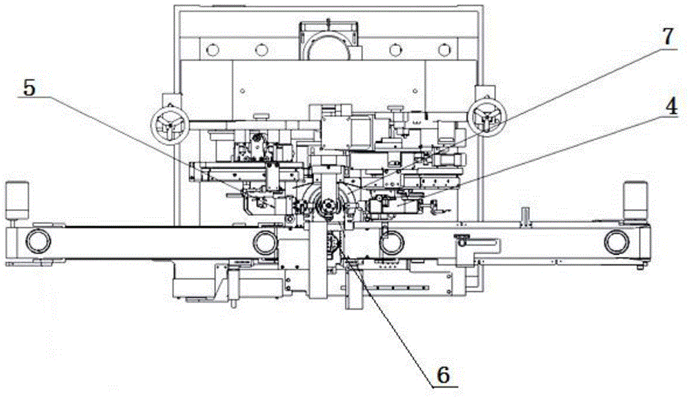
[0037] A feed inlet 6 is arranged in the middle of the loading and unloading conveying mechanism 2, a main shaft 7 is arranged on the rear side of the feeding inlet 6, and an inner hole centering part 8 is arranged on the upper en...


PUM


Abstract

The invention discloses conical/cylindrical linear rollaway nest superfinishing equipment. The conical/cylindrical linear rollaway nest superfinishing equipment comprises an operating table and a material feeding and discharging conveying mechanism arranged on the operating table, wherein a big reciprocating and small vibrating mechanism, a rollaway nest superfinishing swinging head and a flange superfinishing swinging head are further arranged on the operating table; a feeding opening is formed in the middle of the material feeding and discharging conveying mechanism; a main shaft is arranged on the back side of the feeding opening; an inner hole centering component is arranged at the upper end of the main shaft; the big reciprocating and small vibrating mechanism comprises a big reciprocating mechanism and a small vibrating mechanism; the big reciprocating mechanism and the small vibrating mechanism are connected through a first connecting plate; a first skipping component is arranged on the back side of the rollaway nest superfinishing swinging head; a second skipping component is arranged on the back side of the flange superfinishing swinging head; both the rollaway nest superfinishing swinging head and the flange superfinishing swinging head are driven by the big reciprocating and small vibrating mechanism for superfinishing. The conical/cylindrical linear rollaway nest superfinishing equipment performs rollaway nest superfinishing and flange superfinishing at the same time, is simplex in rollaway nest superfinishing vibration and stable and reliable in working conveying, and can meet superfinishing requirements of a high-precision workpiece.

Description

technical field [0001] The invention belongs to the technical field of superprecision bearings, and in particular relates to superprecision equipment for conical / cylindrical linear raceways. Background technique [0002] In the bearing manufacturing process, superfinishing is the last and most important process of bearing processing. The existing conical / cylindrical linear raceway superfinishing equipment has the following problems: (1) The oscillating mechanism used on the superfinishing machine tool is connected with a rotating shaft on the motor shaft through a coupling, and the rotating shaft Two symmetrical balance weights are installed on both sides of the bottom with a crank through the balance wheel. A ram is installed under the rotating shaft with a crank, a slide seat and its driving wheel, and an oilstone clip is installed at the lower end of the ram. This traditional The oscillating mechanism of the ultra-precision equipment adopts the crank-connecting rod mecha...

Claims


Application Information

Patent Timeline
IPC IPC(8): B24B19/06
CPCB24B19/06B24B35/00
Inventor 刘晓民
Owner WUXI LANMA MACHINERY MFR
Why Eureka
Try Eureka