
A hybrid electric vehicle braking energy recovery system and method based on hydrostatic transmission

A technology of braking energy recovery and hybrid vehicles, which is applied in electric braking systems, hybrid vehicles, motor vehicles, etc., can solve the problems of wasting braking energy, high power generation speed of difficult motors, and inability to convert and store kinetic energy of vehicles. Achieve the effect of preventing battery overcharging and prolonging service life

Inactive Publication Date: 2017-09-29
ARCHITECTURAL ENG INST GENERAL LOGISTICS DEPT P L A
View PDF6 Cites 0 Cited by
  • Summary
  • Abstract
  • Description
  • Claims
  • Application Information

AI Technical Summary

Problems solved by technology

[0003] Among them, in Scheme 1, due to the small adjustable range of the transmission ratio of the existing transmission system, it is difficult for the motor to reach and maintain a high power generation speed during braking, which leads to the inability to convert the kinetic energy of the vehicle into electrical energy for storage in a timely manner.
In addition, this also leads to the fact that the power generation system cannot meet the braking torque requirements of the vehicle and must be assisted by mechanical braking, which wastes a lot of braking energy and limits the improvement of the braking energy recovery rate of the vehicle.
The development of CVT technology and hydraulic torque converter technology has improved this problem to some extent, but it is far from satisfactory
Hydrostatic transmission vehicles generally use scheme 3 for braking energy recovery. The power density of the accumulator is high, and energy recovery can be performed quickly and efficiently in the initial stage of energy recovery. However, its energy density is limited, and accumulators are required to store a large amount of energy. It is very bulky and also affects the hydraulic tank volume, which is not allowed in the layout of the vehicle

Method used


Image

  • A hybrid electric vehicle braking energy recovery system and method based on hydrostatic transmission
  • A hybrid electric vehicle braking energy recovery system and method based on hydrostatic transmission
  • A hybrid electric vehicle braking energy recovery system and method based on hydrostatic transmission

Examples


Embodiment Construction

[0044] In order to make the technical problems, technical solutions and beneficial effects solved by the present invention clearer, the present invention will be further described in detail below in conjunction with the accompanying drawings. It should be understood that the specific embodiments described here are only used to explain the present invention, not to limit the present invention.

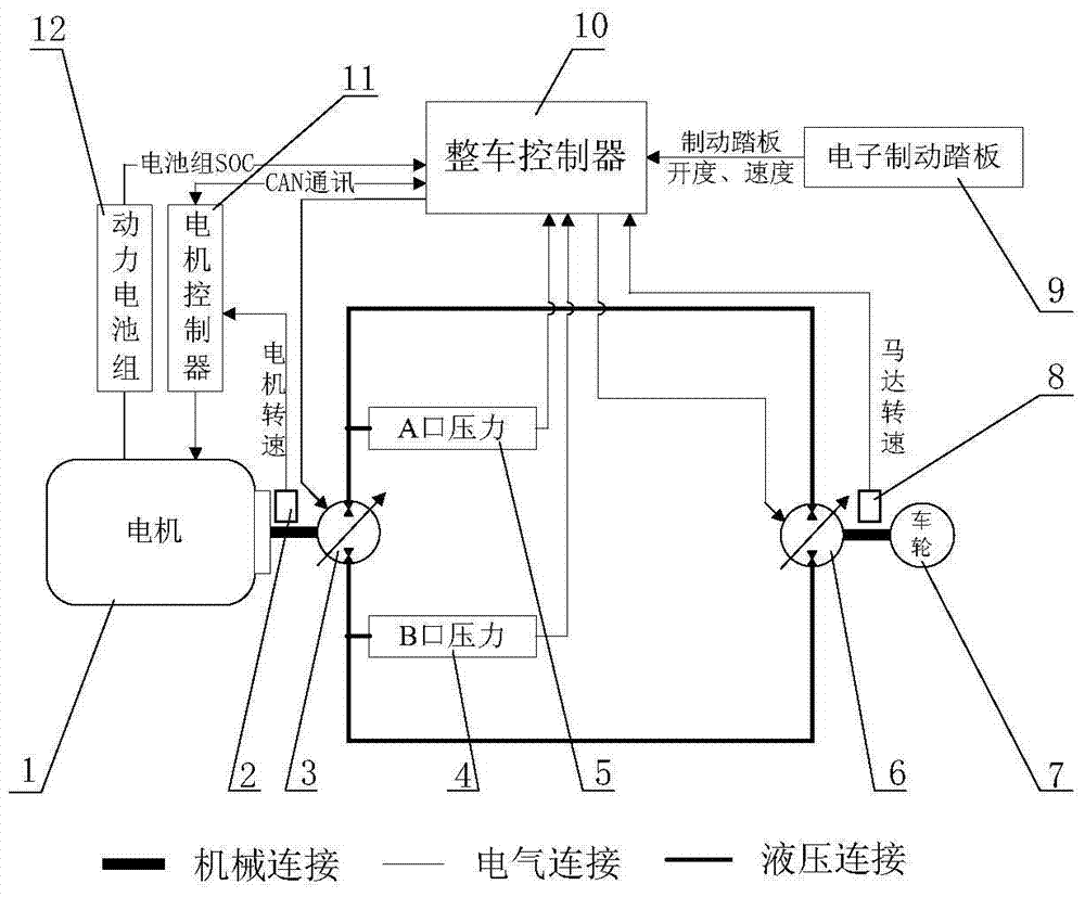
[0045] refer to figure 1 , the hybrid vehicle in the present invention adopts an oil-electric hybrid power source, including a motor 1 electrically connected to a vehicle controller (ECU) 10, a motor controller 11, a hydraulic pump motor mechanism and related hydraulic valve parts, electronic components Moving pedal 9, motor speed sensor 2, hydraulic motor speed sensor 8, hydraulic pump port A pressure sensor 5, hydraulic pump port B pressure sensor 4, power battery pack 12 and power battery pack SOC value sensor, etc., wherein the hydraulic pump motor mechanism includes The first hydr...


PUM


Abstract

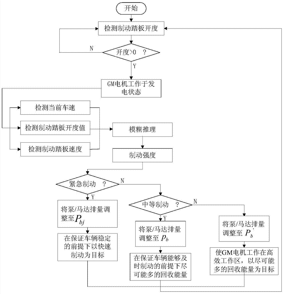
The invention relates to a system and method for recovering the brake energy of a hybrid electric vehicle based on hydrostatic transmission. The system comprises a power battery group, an electronic brake pedal of the hybrid electric vehicle, and a motor, a first hydraulic pump motor mechanism, a second hydraulic pump motor mechanism and wheels which are sequentially connected, wherein whether the hybrid electric vehicle is in a brake state or not is judged according to the open degree of the electronic brake pedal; when the hybrid electric vehicle is in the brake state, the motor is enabled to work in an electricity generating state and charge the power battery group, a brake energy recovering structure reversely dragging the motor to generate electricity by a hydraulic system in the brake process is formed, and hydraulic energy is converted into electric energy to be stored in the power battery group; the delivery capacity of the first hydraulic pump motor mechanism and the second hydraulic pump motor mechanism are regulated according to brake strength values, the running of the motor in an efficient electricity generating zone is ensured, and the maximum conversion and recovery of the brake energy are realized.

Description

technical field [0001] The invention relates to the field of braking energy recovery, in particular to a hybrid vehicle braking energy recovery system and method based on hydrostatic transmission. Background technique [0002] With the depletion of fossil resources such as oil and natural gas and the increasingly severe environmental problems, various energy-saving technologies for vehicles have been increasingly developed and applied. Braking energy recovery is an effective vehicle energy-saving technology. It reduces the energy waste when the vehicle is running and improves the effective conversion rate of energy by recycling the braking energy of the vehicle. The commonly used energy recovery strategies are mainly divided into the following three types: 1) When a vehicle with a gearbox, CVT or torque converter brakes, the kinetic energy of the vehicle is used to drive the generator to generate electricity through the transmission system, and the generated electric energy ...

Claims


Application Information

Patent Timeline
IPC IPC(8): B60W10/08B60W10/18B60W10/30B60W10/26B60W20/00B60L7/10B60W20/40
CPCB60W10/08B60W10/103B60W30/18127B60W2510/081B60W2510/104B60W2510/244B60W2540/12B60W2710/086B60W2710/1088
Inventor 杨立浩朱从民张波宋昆李璐王卫青赫思宇
Owner ARCHITECTURAL ENG INST GENERAL LOGISTICS DEPT P L A
Learn More