Single-shot laser pulse detection device

A detection device, laser pulse technology, applied in the direction of the instrument, can solve the problems of no measurement method, single-shot measurement, low repetition frequency pulse measurement time-consuming, etc., to achieve the effect of improving the dynamic range

Active Publication Date: 2015-06-10
INST OF PHYSICS - CHINESE ACAD OF SCI
View PDF5 Cites 19 Cited by
  • Summary
  • Abstract
  • Description
  • Claims
  • Application Information

AI Technical Summary

Problems solved by technology

Although these traditional ultrafast laser measurement methods, such as FROG, SPIDER measurement and application, have hundreds of literature reports, they basically only involve the measurement of low-power lasers, and they need repeated point-by-point scanning to measure. The measurement of low repetition frequency pulses is very time-consuming and cannot be used for single-shot measurement, and the measurement method involving large dynamic range and high sensitivity is not yet perfect. Although some variant devices can be used for single-shot measurement, it is limited to two beams The method of intersecting and summing light with large angle tilt and transforming the time delay quantity into the space position quantity needs to be further studied and explored.
At present, there are relatively few reports on the large dynamic range signal-to-noise ratio measurement method for single-shot measurement at home and abroad, and there is no ready-made standard for the measurement method. Continue to explore new ways to accomplish this simultaneous requirement: a) single measurement, b) amplitude dynamic range over 10 orders of magnitude, c) 8 orders of magnitude time window, and d) extremely challenging fidelity reliability sex detection task

Method used


Image

  • Single-shot laser pulse detection device
  • Single-shot laser pulse detection device
  • Single-shot laser pulse detection device

Examples


Embodiment 1

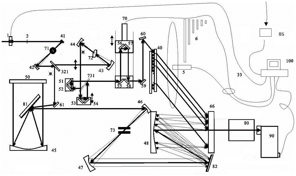
[0082] Such as figure 2 As shown, the trigger 85 is controlled by the computer 100 to trigger the pulse generating device (not shown in the figure) to generate a single laser pulse to be measured, and then the computer 100 controls the opening time of the electric shutter 1. When the laser pulse to be measured passes through the electric shutter When 1 (Shutter), the single-shot laser pulse detection device and the pulse generation device run synchronously, reducing the stray light in the instrument and improving the signal-to-noise ratio of the instrument itself. Make the laser pulse polarization deflection to be measured by 45 degrees by the half-wave plate 2 afterwards, to adjust the light splitting ratio; then pass through the third spatial filter (Spatial Filter), the soft edge diaphragm ceramic aperture 71 is arranged at its focal point, is to make the laser pulse to be measured become a super-Gauss flat-top beam, and expand the beam aperture M1 times simultaneously; th...

Embodiment 2

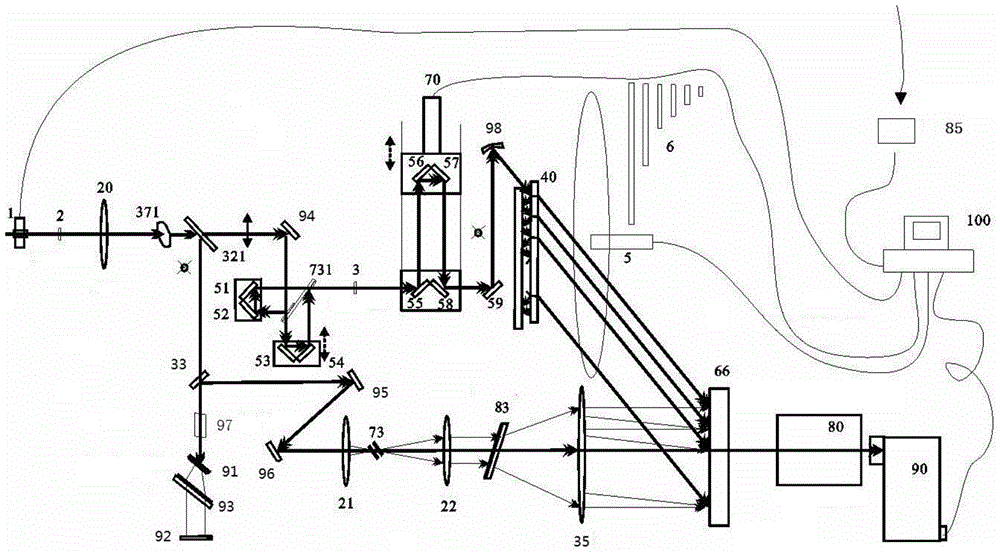
[0088] Such as image 3 As shown, the trigger 85 is controlled by the computer 100 to trigger the pulse generating device (not shown in the figure) to generate a single laser pulse to be measured, and then the computer 100 controls the opening time of the electric shutter 1. When the laser pulse to be measured passes through the electric shutter At 1, the single-shot laser pulse detection device and the pulse generation device run synchronously, reducing the stray light in the instrument and improving the signal-to-noise ratio of the instrument itself. After that, the polarization of the laser pulse to be measured is deflected by the half-wave plate 2 to meet the phase matching requirements of the nonlinear crystal (ooe), so as to adjust the splitting ratio; frequency light, so that the fundamental frequency light and the frequency doubled light are exactly perpendicular to each other, and the input pulse is divided into two paths by the proportional beam splitter 321: the upp...

Embodiment 3

[0093] Such as Figure 4 As shown, the trigger 85 is controlled by the computer 100 to trigger the pulse generating device (not shown in the figure) to generate a single laser pulse to be measured, and then the computer 100 controls the opening time of the electric shutter 1. When the laser pulse to be measured passes through the electric shutter At 1, the single-shot laser pulse detection device and the pulse generation device run synchronously, reducing the stray light in the instrument and improving the signal-to-noise ratio of the instrument itself. After that, the polarization of the laser pulse to be measured is deflected by the half-wave plate 2 to meet the phase matching requirements of the nonlinear crystal (ooe), so as to adjust the splitting ratio; frequency light, so that the fundamental frequency light and the frequency doubled light are exactly perpendicular to each other, and the input pulse is divided into two paths by the proportional beam splitter 321: the up...


PUM


Abstract

The invention provides a single-shot laser pulse detection device. The single-shot laser pulse detection device comprises a detection light path for transmitting baseband detection light pulses, a reference light path for transmitting frequency-doubled reference light pulses, a dual-pulse generator for obtaining dual-pulses having a first time delay and transmitted collinearly along the reference light path, a light pulse converter for converting the dual-pulses into a series of dual-pulse form sub-pulses mutually delayed in time, separated from each other in space and propagated in parallel basically, a pulse stretcher for translating each frequency component of the baseband detection light pulses so as to stretch in the time domain, a dispersor for separating the frequency components in the baseband detection light pulses in space, and a plane detector for generating third-order mutual-correlation pulse signals from the baseband detection light pulses and the sub-pulses from the dispersor. The single-shot laser pulse detection device is capable of accurately measuring the waveform of the femtosecond petawatt lase pulses and solving the problem of difficult diagnosis of ultrafast and ultrastrong pulses large in dynamic range.

Description

technical field [0001] The invention relates to the technical field of engineering optics application, in particular to a single-shot laser pulse detection device. Background technique [0002] In the 1980s, scientists at the University of Rochester in the United States proposed chirped pulse amplification technology (CPA), which made ultra-high-power ultra-fast laser pulses possible (see D. Strickland and G. Mourou, Opt. Commun. 56, 219( 1985). Based on this principle and technology, several laboratories in the world have obtained a peak power breakthrough PW (petawatt, 10 15 W) single ultra-intensive laser output. How to measure the contrast of this type of laser is a major concern and affects the development of this laser research. [0003] Generally, in the background signal of the amplified laser pulse, there are some noise pulses with relatively high intensity, and their existence will have adverse effects on the results of physical experiments. An excessively high ...

Claims


Application Information

Patent Timeline
Patent Type & Authority Applications(China)
IPC IPC(8): G01J11/00
Inventor 李铭魏志义王兆华沈忠伟范海涛
Owner INST OF PHYSICS - CHINESE ACAD OF SCI
Why Eureka
Try Eureka