A zigzag tension pressure sensor

A pull-pressure sensor and sensor technology, applied in the sensor field, can solve the problems of increasing the sensor volume, complicated use and installation, and small application scope, and achieve the effects of improving compatibility and application scope, convenient processing, and less restrictions on use sites.

Active Publication Date: 2017-09-01
HANGZHOU XINJIAN ELECTRONICS
View PDF10 Cites 0 Cited by
  • Summary
  • Abstract
  • Description
  • Claims
  • Application Information

AI Technical Summary

Problems solved by technology

[0004] The strain gauges and other accessories of the above sensors are located outside the main body of the sensor, which increases the volume of the sensor and is easily damaged during use, and the strain gauges are attached to the force center line of the sensor elastic body, because of the error of the patch or processing , there are more or less eccentric load phenomena in the actual force measurement. Although it is more accurate in vertical measurement, when the measured object deviates from the test center line, errors will also occur. The greater the deflection, the greater the error
In addition, the two ends of the sensor are connected to external parts through screw holes, which is complicated to use and install, and there are many accessories, which increases the cost, and the form is single, the compatibility is poor, and the scope of application is small
The column type tension pressure sensor also has the same disadvantages as the S type tension pressure sensor

Method used


Image

  • A zigzag tension pressure sensor
  • A zigzag tension pressure sensor

Examples


Embodiment approach 1

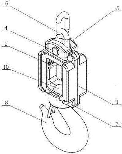
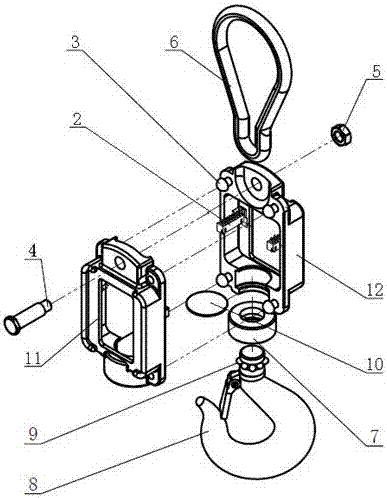
[0019] Embodiment 1: The main body structure of the sensor 1 remains unchanged, the upper connecting parts are the structure of the shaft pin 4 and the nut 5, and the structure of the shaft pin 4 and the nut 5 is also connected to the external member 6, which can be a chain or a shackle; the lower part is connected Parts are hook 8 structures.

Embodiment approach 2

[0020] Embodiment 2: The main body structure of the sensor 1 remains unchanged, and the upper and lower connecting parts are both the shaft pin 4 and the nut 5 structure, and the shaft pin 4 and the nut 5 structure are also connected to the external component 6, and the external component 6 can be a chain or a shackle .

Embodiment approach 3

[0021] Embodiment 3: The main structure of the sensor 1 remains unchanged, the upper connecting part is the structure of the hook 8; the lower connecting part is the structure of the shaft pin 4 and the nut 5, and the structure of the shaft pin 4 and the nut 5 is also connected to the external member 6, and the external member 6 Can be chain or shackle.


PUM


Abstract

A mouth-shaped pull-pressure sensor comprises a sensor body and strain gauges. The middle of the sensor body is hollowed to be mouth-shaped, the strain gauges are arranged on two sides of the inside of the sensor body, and the sensor body can be integrally formed and can also be formed by combining two sensor bodies. The mouth-shaped pull-pressure sensor is simple in structure, convenient to machine, accurate in measurement and high in deflection resistance, eccentric load is overcome, the structure of the sensor can serve as a portion of a shell, the strain gauges and other accessories inside the sensor are effectively protected, space is saved, the size of the sensor is reduced, the sensor body is provided with a structure connected with the outside, materials are saved, cost is reduced, using places are less limited, and compatibility and the applicable range of the sensor are expanded.

Description

technical field [0001] The invention relates to the technical field of sensors, in particular to a zigzag tension pressure sensor. Background technique [0002] The load cell is actually a device that converts the mass signal into a measurable electrical signal output. It consists of one or more elastic bodies that can deform after being stressed, and a resistance strain gauge that can sense this deformation. The bridge circuit (such as the Wheatstone bridge), and the adhesive that can fix the resistance strain gauge on the elastic body and conduct the strain, and the sealant that protects the electronic circuit are composed of three parts. [0003] Tension and pressure sensors are a large category of weighing load cells, and their shapes mainly include S-type and column-type. Among them, taking the S-type tension pressure sensor as an example, its main structure includes a sensor body, a sensor housing and a signal line. The sensor body is equipped with a sensor housing, a...

Claims


Application Information

Patent Timeline
Patent Type & Authority Patents(China)
IPC IPC(8): G01L1/04
Inventor 杨礼杨越
Owner HANGZHOU XINJIAN ELECTRONICS
Why Eureka
Try Eureka