
Scanning type light source testing system

A scanning light source and testing system technology, applied in the field of online scanning light source light intensity distribution and luminous flux testing system, can solve problems such as difficulty in meeting production line testing requirements, and achieve the effect of convenient query and accurate test results

Active Publication Date: 2015-06-10
CHANGZHOU INST OF OPTOELECTRONICS TECH
View PDF6 Cites 0 Cited by
  • Summary
  • Abstract
  • Description
  • Claims
  • Application Information

AI Technical Summary

Problems solved by technology

[0009] To sum up, the integrating sphere test and goniophotometer are limited by the test method and equipment size, and basically can only be measured under laboratory conditions. To correctly test the luminous flux and light intensity distribution curve of the light source under test, the test must also be considered. The efficiency of the test equipment and the ease of operation of the test equipment must be adapted to the rapid test of the production line and the installation of the light source under test. The existing test devices are difficult to meet the test requirements of the production line.

Method used


Image

  • Scanning type light source testing system
  • Scanning type light source testing system
  • Scanning type light source testing system

Examples


Embodiment 1

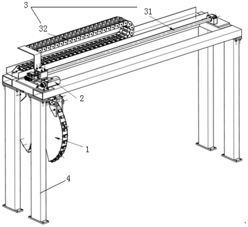
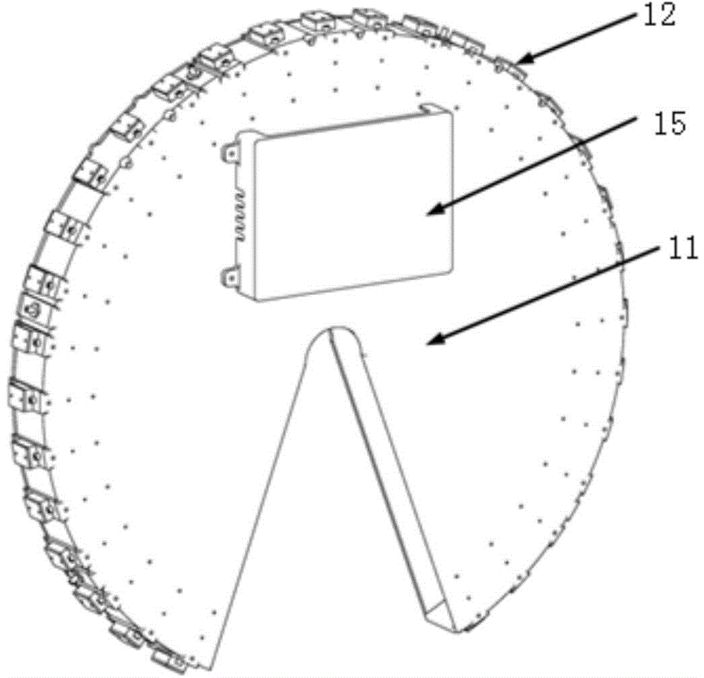
[0032] See figure 1 , a scanning light source testing system of the present embodiment comprises an optical test disk 1, a drive mechanism 2, a transmission mechanism 3 and a frame 4; the optical test disk 1, the drive mechanism 2 and the transmission mechanism 3 are all arranged on the frame 4; the driving mechanism 2 drives the transmission mechanism 3 to drive the optical test disc 1 to scan along the length direction of the light source to be tested; the optical test disc 1 includes a disc body 11 and a photoelectric sensor arranged on the arc surface of the disc body 11 12. The driving mechanism 2 is a motor; the transmission mechanism includes a ball screw 31 and a cable drag chain 32 . The optical test disc 1 is connected to the ball screw 31 through the connecting component, and the motor drives the ball screw 31 to move, so that the optical test disc 1 scans along the ball screw 31 to obtain light intensity test data, protected by the cable drag chain 32 The data ac...

Embodiment 2

[0036] Embodiment 2 is the first rotary scanning test system, such as Figure 4 As shown, the photoelectric sensor 12 is fixed on the disc body 11 by screws. Driven by the rotating motor, the photodetector 12 rotates by itself from 0° to 360° under the drive of the rotating motor, and the disc body 11 performs linear scanning operation. After completion, the distribution of light intensity within the entire solid angle range of the light source can be obtained.

Embodiment 3

[0038]Embodiment 3 is another rotary scanning test system. The photoelectric sensor 12 is fixed on the disc body 11 by screws. Driven by the rotating motor, the disc body 11 rotates from 0° to 360° to scan and simultaneously Driven by the driving mechanism to scan along the length direction of the light source to be measured, after the scanning is completed, the light intensity distribution within the entire solid angle range of the light source can be obtained.


PUM


Abstract

The invention discloses a scanning type light source testing system. The system comprises an optical testing disc, a driving mechanism, a transmission mechanism and a rack; the optical testing disc, the driving mechanism and the transmission mechanism are arranged on the rack; the driving mechanism drives the transmission mechanism to drive the optical testing disc to scan in the length direction of a light source to be tested; the optical testing disc comprises a disc body, and a photoelectric sensor arranged on an arc-shaped surface of the disc body. With the adoption of the device, the luminous flux and light strength distribution curves of each light source can be quickly and accurately tested; a scanning testing device can be conveniently combined with a production line or a testing line of a plant, so as to achieve the integral production and testing.

Description

technical field [0001] The invention relates to an online scanning light source light intensity distribution and luminous flux testing system. Background technique [0002] Since the launch of the national semiconductor lighting project in 2003, my country's semiconductor lighting industry has made great progress, and the development momentum of semiconductor lighting packaging and application products is particularly strong. However, due to the many luminous characteristics of LED application products, the detection methods are very different from traditional light sources and lamps, which makes the detection of semiconductor lighting products, especially the online detection, a challenge. [0003] There are mainly two methods of online testing: cold measurement and hot measurement. At present, most of the more common online tests use the cold measurement method. The cold-state measurement of semiconductor lighting products has some insurmountable disadvantages, and it can...

Claims


Application Information

Patent Timeline
Patent Type & Authority Applications(China)
IPC IPC(8): G01M11/02
Inventor 金亚方刘石神陈要玲蒋威刘从峰
Owner CHANGZHOU INST OF OPTOELECTRONICS TECH
Learn More