Multichannel Hall rotation speed sensor

A Hall speed sensor technology, applied in instrumentation, linear/angular velocity measurement, velocity/acceleration/impact measurement, etc., can solve the problems that cannot meet the speed measurement requirements of high-speed motors of EMUs, the number of channels is small, and there is no signal output, etc., to achieve Strong vibration resistance, large induction air gap and wide speed measurement range

Active Publication Date: 2015-06-10
HUNAN XIANGYI RAILROAD LOCOMOTIVE ELECTRICAL EQUIP
View PDF9 Cites 21 Cited by
  • Summary
  • Abstract
  • Description
  • Claims
  • Application Information

AI Technical Summary

Problems solved by technology

[0010] In view of this, the purpose of the present invention is to provide a multi-channel Hall speed sensor, which solves the problems in the prior art that cannot meet the speed measurement requirements of the high-speed motor of the EMU, the number of channels is too small, and there is no signal output when the locomotive is at low speed. question

Method used


Image

  • Multichannel Hall rotation speed sensor
  • Multichannel Hall rotation speed sensor
  • Multichannel Hall rotation speed sensor

Examples


Embodiment 1

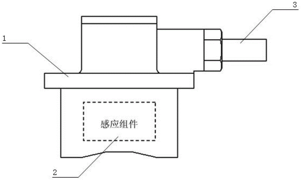
[0066] as attached figure 1 As shown, the sensor at least includes a housing 1 and an induction assembly 2, and the housing 1 is used to install the sensor on the rolling stock wheel set (rolling stock wheel set axle box end cover) or the motor non-drive end cover or the motor drive end cover, And protect its internal devices. The induction component 2 is installed in the casing 1, and is used to sense the rotation speed of the locomotive wheel shaft or motor shaft, and generate 3 to 8 electrical pulse signals whose frequency is proportional to the rotation speed and at least 2 electrical pulse signals with a specific phase difference. The induction assembly 2 is arranged on the top of the speed measuring gear 5, and the speed measuring gear 5 is arranged on the locomotive vehicle wheel shaft or the motor shaft 7, and rotates with the rotation of the locomotive vehicle wheel shaft or the motor shaft 7.

[0067] The sensing component 2 further includes a power processing circu...

Embodiment 2

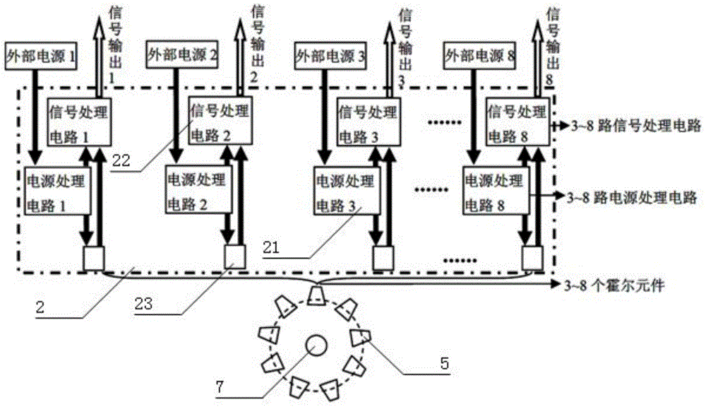
[0069] as attached image 3 As shown, in Embodiment 1, a power processing circuit 21 processes the external power supply to provide power for the multi-channel Hall elements 23 respectively, and a signal processing circuit 22 processes the output signals of the multi-channel Hall elements 23 The technical solutions are different. In this embodiment, the multi-channel Hall speed sensor has multiple power supply processing, signal acquisition and signal processing channels, and the power processing circuit 21, signal processing circuit 22, and Hall element 23 in each channel are electrically independent, that is, It is said that each channel includes an independent power processing circuit 21 and a signal processing circuit 22 . Alternatively, two channels with a specific phase difference share a power supply.

[0070] In the above-mentioned embodiment 1 and embodiment 2, the installation position of at least two Hall elements 23 in the sensor that output the specific phase di...

Embodiment 3

[0076] as attached Figure 4 As shown, in this embodiment, the sensing surfaces of 3 to 8 Hall elements 23 are close to the speed measuring gear 5, and there is an arc surface equidistant from the axis center of the speed measuring gear 5, and the arc surface is connected to each Hall element The sensing surfaces of the elements 23 are all tangent, and the sensing surfaces of 3-8 Hall elements 23 are distributed on multiple planes tangent to the arc surface. At this time, the installation positions of the sensing surfaces of 3 to 8 Hall elements 23, the parameters of the speed measuring gear 5 and the installation air gap of the sensor further conform to the following functional relationship:

[0077] D = ( z + 2 ) m 2 + σ

[0078] θ = 2 ...


PUM


Abstract

The invention discloses a multi-channel locomotive speed measurement hall revolution speed transducer and an installation method thereof. The multi-channel locomotive speed measurement hall revolution speed transducer comprises an induction module and a processing circuit board, wherein the processing circuit board comprises a power supply processing circuit and a signal processing circuit; after an external power supply input signal is processed by the power supply processing circuit, power is respectively supplied to the induction module and the signal processing circuit; the induction module comprises more than two groups of double-channel hall elements and is used for transmitting pulse signals induced and changing with the rotation of a speed measuring gear to the signal processing circuit; after the signal processing circuit is used for amplifying and shaping the pulse signals, the four processed signals are output to an upper computer. The locomotive speed measurement multi-channel hall revolution speed transducer can be used for solving the problems in the prior art that the high-speed speed measurement requirements of motor train units cannot be met, few number of channels are available and signals are not output during the low speed running of a locomotive. The multi-channel locomotive speed measurement hall revolution speed transducer is in non-contact with the speed measuring gear, free of abrasion, simple in a production debugging technology, convenient to install, large in induction air gap and wide in speed measurement range and temperature adaptive range and has strong vibration resistance and anti-disturbance performance.

Description

technical field [0001] The invention relates to a sensor device, in particular to a multi-channel non-contact Hall speed sensor used for speed measurement of rail transit vehicles such as locomotives, bullet trains, and high-speed rail trains. Background technique [0002] With the increasing speed and carrying capacity of domestic trains today, safe driving has also received more and more attention and attention. This requires that the train must receive the current running speed signal accurately and reliably. At present, the sensors used in locomotive speed measurement mainly use photoelectric speed sensors, Hall speed sensors and magnetoelectric speed sensors. [0003] The existing photoelectric speed sensor is installed at the end of the locomotive shaft to provide the running speed and running direction for the locomotive. The sensor input shaft is connected to the measured wheel shaft of the locomotive, and the measured wheel shaft drives the sensor input shaft to ro...

Claims


Application Information

Patent Timeline
Patent Type & Authority Applications(China)
IPC IPC(8): G01P3/481
Inventor 彭建红钟真贺雄
Owner HUNAN XIANGYI RAILROAD LOCOMOTIVE ELECTRICAL EQUIP
Why Eureka
Try Eureka