Method for adjusting nonuniform machining allowance of propeller

A technology of machining allowance and adjustment method, which is applied in the directions of instrumentation, calculation, electrical digital data processing, etc., and can solve problems such as uneven machining allowance of propellers

Active Publication Date: 2015-06-10
HUST WUXI RES INST +1
View PDF2 Cites 2 Cited by
  • Summary
  • Abstract
  • Description
  • Claims
  • Application Information

AI Technical Summary

Problems solved by technology

[0004] The purpose of the present invention is to solve the problems mentioned in the above background technology section by a method for adjusting the uneven machining allowance of the propeller

Method used


Image

  • Method for adjusting nonuniform machining allowance of propeller
  • Method for adjusting nonuniform machining allowance of propeller
  • Method for adjusting nonuniform machining allowance of propeller

Examples


Embodiment Construction

[0047] The present invention will be further described below in conjunction with drawings and embodiments. It should be understood that the specific embodiments described here are only used to explain the present invention, but not to limit the present invention. In addition, it should be noted that, for the convenience of description, only some parts related to the present invention are shown in the accompanying drawings but not the whole content. Unless otherwise defined, all technical and scientific terms used herein are related to the technical field of the present invention. The skilled person generally understands the same meaning. The terms used herein are for describing specific embodiments only, and are not intended to limit the present invention.

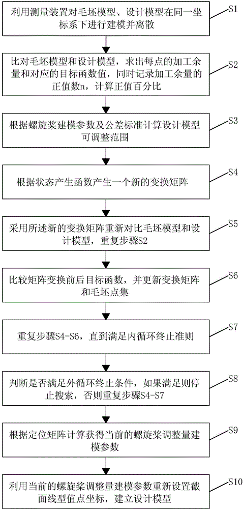
[0048] Please refer to figure 1 as shown, figure 1 The flow chart of the method for adjusting the uneven machining allowance of the propeller provided by the embodiment of the present invention.

[0049] In this embodi...


PUM


Abstract

The invention discloses a method for adjusting a nonuniform machining allowance of a propeller. The method overcomes the defect that the nonuniform machining allowance of the propeller needs to be manually adjusted, the pose of a design model is automatically adjusted according to a technological tolerance and the current machining allowance distribution situation, quick matching between a propeller blank model and the design model is achieved on the premise that the tolerance standard is met, the situation that the machining allowance of a blank is uniform is guaranteed, and machining quality of blades is improved.

Description

technical field [0001] The invention relates to the technical field of on-line measurement and processing of propellers, in particular to a method for adjusting uneven machining allowances of propellers. Background technique [0002] The propeller is a very important typical casting part in the shipbuilding industry, and its manufacturing quality has a huge impact on the concealment, dynamic performance and stability of the ship. Traditional propeller manufacturing adopts the process of measuring first and then processing. Engineers use blank measurement to check whether the blank has a machining allowance, and determine the machining area and allowance. In the process of analyzing blank measurement data, there are often problems with excessive cutting amount in some areas and no cutting amount in some areas. Engineers can manually adjust the pose of the design model to solve the above problems, but the adjustment process is time-consuming and inefficient. With the develop...

Claims


Application Information

Patent Timeline
Patent Type & Authority Applications(China)
IPC IPC(8): G06F17/50
Inventor 彭芳瑜闵壮郑妍闫蓉李斌
Owner HUST WUXI RES INST
Why Eureka
Try Eureka